Download
1 / 29
300 likes | 529 Views
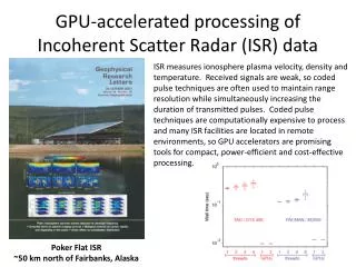
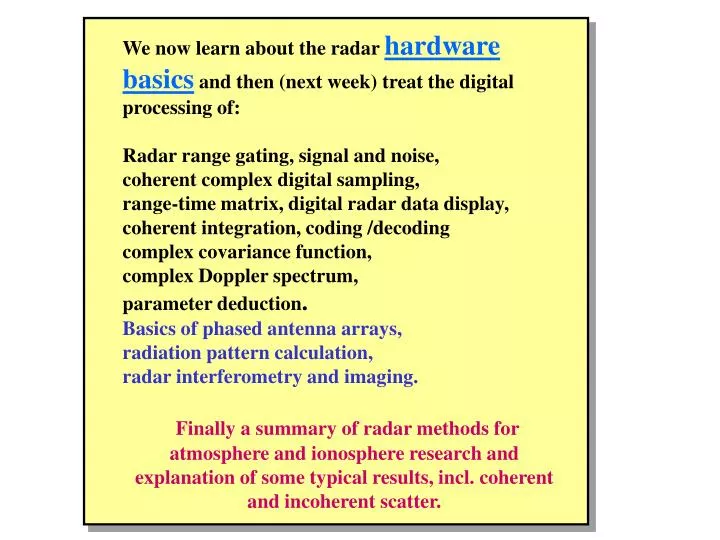
We now learn about the radar hardware basics and then (next week) treat the digital processing of: Radar range gating, signal and noise, coherent complex digital sampling, range-time matrix, digital radar data display, coherent integration, coding /decoding complex covariance function,

E N D
We now learn about the radar hardware basics and then (next week) treat the digital processing of: Radar range gating, signal and noise, coherent complex digital sampling, range-time matrix, digital radar data display, coherent integration, coding /decoding complex covariance function, complex Doppler spectrum, parameter deduction. Basics of phased antenna arrays, radiation pattern calculation, radar interferometry and imaging. Finally a summary of radar methods for atmosphere and ionosphere research and explanation of some typical results, incl. coherent and incoherent scatter.
Radar System Design and Data Processing
The ESR Receiver - Cryo-cooled (15 K) GaAsFET preamplifier, feeding into three parallel, high dynamic range dual superhets, employing + 23 dBm balanced mixers 1st IF = 70 MHz, 2nd IF = 7.5 ± 1.8 MHz - Receiver chain 1 dedicated to ion linereception fixed at 500 ± 1.8 MHz - Chains II and 111 used for plasma linereception, tunable over 484 – 516 (± 1.8) MHz - Sample of transmitted signal detected at first mixer - 2nd IF output signals at -10 dBm digitized by continuously running10 MHz, 12 bit A/D converters - Each 10 MHz data stream fed into several digital back end channels in parallel - Detection at nonzero IF results in: DC offset, gain imbalance, quadrature phase errors and unequal filter responses are avoided altogether. - Major advantage over muIti-channel base-band detection system
The ESR Antenna - 32 m shaped Cassegrain geometry, custom design - Designed, built by Kamfab-NTG-Ticra- Dielectric - high gain, 42.5 dBi at 500 MHz - low system noise temperature, 65 K at 500 MHz - low sidelobes - mechanically fast: 2.2 -2.8 degrees per second, can swing through 180 degrees in elevation - Dedicated real time control computer running OS-9 - Position servo loop closes numerically in computer
The ESR Transmitter • - Designed / built by Harris TVT, Cambridge, U.K. • - Basically a combination of 4 (8) standard UHF • TV transmitters, slightly modified, producing 500 kW (1 MW) • at 25 % duty cycle • (highest ever used in a pulsed ISR). • Pulse modulator is all solid state, runs at 25 kV • - Instantaneous power BW is 500 ± 2 MHz, • range resolution down to 40 m can be achieved • - Advanced DDS / heterodyne exciter providing • - theoretically unlimited number of TX frequencies • - pulse-to-pulse multi-frequency phase coherency • - linear chirp (later) • - possibilities for adding pseudo-random BPSK • - Transmitted waveform sampled and processed by receiver: • corrections for transmitter effects in the data analysis can • be done exactly, not only from models (a first as a routine • feature) • - Designed for unattended operation
LATEST REVISION OF RECEIVER’S BLOCK DIAGRAM IF MON1 I-1 VA LPF LIM DC BL LN BPF MIX IFA BL ATT IFA DC QM LIM LIM LIM LIM RF IN1 Q-1 LPF VA IF MON2 I-2 VA LPF LIM DC BL LN BPF MIX IFA BL ATT IFA DC QM RF IN2 Q-2 LPF VA IF MON3 I-3 VA LPF LIM DC BL LN BPF QM MIX IFA BL ATT IFA DC RF IN3 Q-3 LPF VA LIM AMP 120 MHz OUT AMP 1:4 DIV LIM AMP 1:4 DIV MIX 150 MHz OUT NC 30 MHz 1:4 FREQ DIV AMP REF (Obtained from MO) 120 MHz MO 30 MHz OUT NO DC SUPPLY Generation of 120+ΔF and 150+ΔF signals Default radar operation freq is 150 MHz For generation of 150+ΔF signal, LO 120+ΔF signal injected via LO IN 220 Volts AC Mains LO SWITCH LO IN BL SW CONTL
The ESR Digital Signal Processor - Every four back end channels are served by a VME DSP board containing: - two T.I. TMS 320C40 DSPs (2 x 80 Mflops) - 2 x 12 MB local RAM + 16 MB of 21 global dual-port RAM - six DMA controllers + VME bus interface - DSP computes the autocovariance coefficients of the filtered sample stream, averages and stores these in lag profile format or as raw data - DSP also controls NCO and filter settings on a pulse-by-pulse basis - Data output is over dedicated 10 MB/sec DMA link into four CPU, SparcServer 1000
The ESR RX Digital Back End - First known use of fullydigital back end in a scientific radar receiver - Each digital back end channel contains: - a tunable numerical oscillator - a digital complex multiplier - a complex digital FIR filter / decimator - a 2 x 256 kWords ping-pong sample memory
4-PORT DISTRIBUTION SYSTEM FOR THE TX ANTENNA OF THE LAPAN-TRAINERS VHF RADAR Yagi antenna Yagi antenna Yagi antenna Combiner II 1 (2,5 kW) Combiner II 2 Combiner II 4 Combiner III 10 kW RX TX 3 kW TX 1 kW TX 1 kW TX 1 kW
RC Remote Control PC Lab View Software DSP Digital Signal Processing PRP TRAINERS - Radar-System( Phase 1/ Phase X ) RFP ADC FLP (Phase 1) PA 10KW MO φ 0/180º ANT ( TX ) 148 MHz 10 W 100 W 1 KW TX 0º 90º I ANT ( RX ) LNA Q RX 1 Picture 0-1 Radar System Schematic
To follow next: Radar range gating, coherent complex digital sampling, range-time matrix, digital radar data display, coherent integration, complex covariance function, complex Doppler spectrum, parameter deduction. Basics of phased antenna arrays, pattern calculation, radar interferometry. A final summary of radar methods for atmosphere and ionosphere research.