Download
1 / 12
120 likes | 319 Views
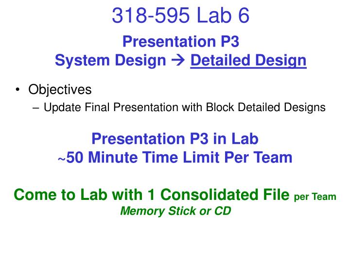
Presentation P3 System Design Detailed Design. Objectives Update Final Presentation with Block Detailed Designs. Presentation P3 in Lab ~50 Minute Time Limit Per Team Come to Lab with 1 Consolidated File per Team Memory Stick or CD. Reuse: Project Presentation P2.

E N D
Presentation P3System Design Detailed Design • Objectives • Update Final Presentation with Block Detailed Designs Presentation P3 in Lab~50 Minute Time Limit Per TeamCome to Lab with 1 Consolidated File per Team Memory Stick or CD
Reuse: Project Presentation P2 • Product Level Slides – IN THIS ORDER ! • Reuse the following slides from P2 (leave out lined items) • All Project Proposals including block diagrams • Team Roster and Background Slides • Recommended Project Description • High Level or User Requirements – What does it do for user? • Perf Requirements Summary • Std Requirements Summary • Basic Business Case • Refined Block Diagram - Block Diagram Description Page • Requirements Spreadsheet: Project Level Tabs (Excel File) • Requirements Spreadsheet: Block Level Tab Flowdowns (Excel File) • Min 1 Page on Key Risk Areas • 1 Page on 3 Key Patents Found for Product Area Labs 1A-B Lab 1C
Reuse/Update Presentation P2 P3 • Product Level Slides - Continued • Product Safety Requirements/Standards Summary Slide(s) • Product EMC Requirements/Standards Summary Slide(s) • Product Level Design Plan Summary & Gantt Chart Slides • Overall Prototype Plan, Interconnection Strategy Labs 2-3
Update Presentation P2 P3 • Block LevelSlides – IN THIS ORDER !! • Block Description and Purpose Slide • Block Key Performance Requirements, Allocated/Associated • Block Key Standard Requirements, Allocated/Associated • Block Breakdown Diagram Slide (Block Diagram of the Block) • Block Signal Input/Output Summary Slide(s) – Lab 1C • Block Schematic - Product Design • 3-4 Bullets on Theory of Operation • Block Bill of Materials - Product Design (Packages, Part Numbers) • Block Detailed Design Calculations & Component Selection • See Appendix Pages • New - Block Schematic – Prototype Design (if different from product) • New – Block Layout – Prototype Design – Lab 5 For Each Block ~10 Min
Presentation P3 • Additional Product Level Slides – Lab 5 • Product Mfg Process Design (Block Diagrams) – Lab 5 • PCB Assembly Process Diagram including all Inspection & Testing • High Level Assembly Process Diagram including all Insp & Testing • Product Overall Master BOM – Lab 5 Labs 2-3
Presentation P3 Additional Block Detailed Design Slide Content Detailed Design Calculations & Component Selections • Device Package Type Rationale • Nominal Resistance, Capacitance, Inductance Values & % Tolerance Calculations • Resistor Compositions, Capacitor Dielectric, Inductor Winding; Selection Rationale • Resistor, Capacitor, Inductor, Diode, Transistor & IC Max Voltage Calculations • Resistor, Inductor, Transistor, Diode, Xfmr, & IC Max Power Calculations • Power Electronics Heat Sink qj Calculations and Max Die Temp Rise Above Ambient • EMC Devices including filters, ferrites, transient absorbers, etc • Safety Devices such as Current Limiters incl Fuses, Breakers, GFCI, etc • Wire Gauges, Interconnect Contact, & Trace Width Ratings • Op-Amp Selections including Ib, Vio, CMRR, Slew Rate, Iout & Error Voltage Calculations • Logic Family Selection including Interface Compatibility, Speed, Power • CPU and/or PLD Types and Clock Speed, Performance Capabilities • Regulator Basic Performances incl % line and % load regulations • Nominal Time Domain Operational Simulations • Nominal Frequency Domain Operational Simulations • Worst Case or Monte-Carlo Simulations • Additional Analog Circuit DFM Analysis as applicable
Passive Discrete Specifications Nominal Adjustment Tolerance Derated Maximum Maximum Maximum Composition Q Factor or Value or Max Range, Around Power Working Constant Surge Dielectric or Frequency Package Value %/Turn Nominal Capacity Voltage Current Current Form Variation Component Resistor Mandatory Mandatory Mandatory Mandatory Mandatory Recommend Recommend Recommend Potentiometer Mandatory Mandatory Mandatory Mandatory Mandatory Mandatory Recommend Recommend Recommend Recommend Fixed Capacitor Mandatory Mandatory Mandatory Mandatory Mandatory Mandatory Recommend Recommend Variable Capacitor Mandatory Mandatory Mandatory Mandatory Mandatory Mandatory Mandatory Recommend Recommend Fixed Inductor Mandatory Mandatory Mandatory Mandatory Mandatory Mandatory Mandatory Mandatory Recommend Variable Inductor Mandatory Mandatory Mandatory Mandatory Mandatory Mandatory Mandatory Mandatory Mandatory Recommend DFM Calculations GuidePassive Discrete Components
All Components Require Some Level of DFM Justification • Passives: Resistors, Capacitors, Inductors, Thermistors • Semiconductors: Diodes, Transistors, SCRs, Triacs, Bridges, Integrated Circuits, etc • Sensors: Temp, Pressure, Humidity, Ph, Moisture, Distance, Proximity, etc • Transducers: Speakers, Microphones, Buzzers, Peizo, etc • Relays: Electro-Mech, Solid State, Reed, Latching • Motors: Drives, Solenoids, Linear Motors, Actuators • Transformers: Auto, Split, Center Tapped, Toroid, RF, Tuning • Batteries: Alkaline, NiCd, NiMH, LiIon, Pb Acid, etc • Interconnects: Wire, Connectors, Terminals, Power Plugs, Cables, Jacks, Plugs, etc • Switches: Toggle, Rocker, Momentary, Breakers, Keyboards, etc • Displays: Lamps, LEDs, Segmented Displays, LCDs, etc • Over Current Protection Devices: Fuses, Breakers, GFCI, Surge Protectors • Over Voltage Protection Devices: Diodes, Fast Clamps, Tranzorbs • Other Safety & EMC Devices: Ferrite Beads, Chokes, Line Filters, Shielding Why was this particular manufacturer’s part number picked? What are the most important part attributes and how have you guaranteed DFM?
Common Analog & Power Subcircuits for DFM Analysis Non-Linear Linear • Comparators • Oscillators (non-sinusoidal, square, sawtooth, etc) • Voltage Limiters and Clamps • Rectifiers and Bridges • Math Functions (multiply, divide) • Log and other Non-linear Amplifiers • Sample and Hold Amplifiers • Envelope & Peak Detectors • Phase Detectors • Phased Locked Loops • Switching Voltage Regulators • Pulse Generators, Debouncers • Multipliers, Modulators, Transmitters, Receivers • Amplifiers and Attenuators • Math Functions (add, subtract) • Oscillators (sinusoidal) • Filters • Voltage Regulators • Voltage References • Analog Drive Displays (Bulbs, LEDs, etc)
Common Digital Subcircuits for DFM Analysis Logic Family Based LSI & VLSI • Adders, Subtractors, Math Units • Magnitude Comparators • Encoders • Decoders • Multiplexers (Mux’s) • Demultiplexers (Dmux’s) • Code Converters • Bus Buffers • Flipflops, Latches, Latching Buffers • Counters, Timers • Pulse Generators • Optical Couplers • CPU’s & Microcontrollers • Analog-Digital Converters • Digital-Analog Converters • Prog Logic Devices, FPGAs • Sequencers • Prog Read Only Memories (Eproms, EEproms) • Random Access Memories (SRAM, DRAM) • Controllers (Serial, Drive, USB, Ethernet) • Logic Input Displays