Download
1 / 44
440 likes | 695 Views
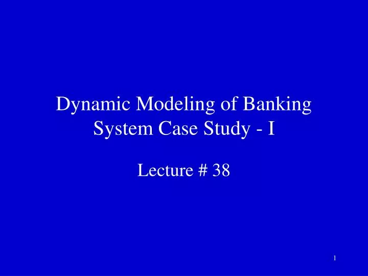
Dynamic Modeling of Banking System Case Study - I. Lecture # 38. Dynamic Modeling. There are two ways to model dynamic behavior

E N D
Dynamic Modeling of Banking System Case Study - I Lecture # 38
Dynamic Modeling • There are two ways to model dynamic behavior • One is the life history of one object as it interacts with the rest of the world; the other is the communication patterns of a set of connected objects as they interact to implement behavior
Dynamic Modeling • The view of an object in isolation is a state machine – a view of an object as it responds to events based on its current state, performs actions as part of its response, and transitions to a new state • This is displayed in state chart diagrams in UML
Dynamic Modeling • The view of a system of interacting objects is a collaboration, a context-dependent view of objects and their links to each other, together with the flow of messages between objects across data links • Collaboration and sequence diagrams are used for this view in UML
Dynamic Modeling • The dynamic model depicts the interaction among the objects that participate in each use case • The starting point for developing the dynamic model is the use case and the objects determined during object structuring
Today’s Topics • We’ll apply the first view of dynamic modeling to the Banking System application that we have been talking about during this course
Dynamic Modeling of Banking System Case Study • The Client Validate PIN and Client Withdraw Funds client use cases are state-dependent use cases. The state-dependent aspects of the use case are defined by the ATM Control object, which executes the ATM statechart
Dynamic Modeling of Banking System Case Study • The Client Validate PIN use case starts with the customer inserting the ATM card into the card reader • The statechart for ATM Control for the Validate PIN use case is shown next
Statechart for ATM Control: Validate PIN Use Case Idle 1.2: Card Inserted / 1.3: Get PIN Waiting for PIN Entry / Display Welcome 2.4: PIN Entered / 2.5: Validate PIN Validating PIN 2.6: Valid PIN / 2.7: Display Menu, 2.7a: Update Status Waiting for Customer Choice
Statechart for ATM Control: Validate PIN Use Case 1: The ATM Customer actor inserts the ATM card into the Card Reader. The Card Reader Interface object reads the card input 1.1: The Card Reader Interface object sends the Card Input Data, containing card ID, start Date, and expiration Date, to the entity ATM Card
Statechart for ATM Control: Validate PIN Use Case 1.2: Card Reader Interface sends the Card Inserted event to ATM Control. As a result, the ATM Control statechart transitions from Idle state (the initial state) to Waiting for PIN state. The output event associated with this transition is Get PIN
Statechart for ATM Control: Validate PIN Use Case 1.3: ATM Control sends the Get PIN event to Customer Interface 1.4: Customer Interface displays the Pin Prompt to the ATM Customer actor
Statechart for ATM Control: Validate PIN Use Case 2: ATM Customer inputs the PIN to the Customer Interface object 2.1: Customer Interface requests Card Data from ATM Card 2.2: ATM Card provides the Card Data to the Customer Interface
Statechart for ATM Control: Validate PIN Use Case 2.3: Customer Interface sends the Customer Info, containing card ID, PIN, start Date, and expiration Date, to the ATM Transaction entity object 2.4: Customer Interface sends the PIN Entered (Customer Info) event to ATM Control. This causes ATM Control to transition from Waiting for PIN state to Validating PIN state. The output event associated with this transition is Validate PIN
Statechart for ATM Control: Validate PIN Use Case 2.5: ATM Control sends a Validate PIN (Customer Info) request to the Bank Server 2.6: Bank Server validates the PIN and sends a Valid PIN response to ATM Control. As a result of this event, ATM Control transitions to Waiting for Customer Choice state. The output events for this transition are Display Menu and Update Status
Statechart for ATM Control: Validate PIN Use Case 2.7: ATM Control sends the Display Menu event to the Customer Interface 2.7a: ATM Control sends an Update Status message to the ATM Transaction 2.8: Customer Interface displays a menu showing the Withdraw, Query, and Transfer options to the ATM Customer actor
Statechart for ATM Control: Withdraw Funds Use Case Idle Terminating Entry / Display Welcome 3.18: Card Ejected / 3.19: Display Ejected Ejecting Waiting for Customer Choice 3.15: Receipt Printed / 3.16: Eject Printing 3.3: Withdrawal Selected / 3.4: Request Withdrawal, 3.4a: Display Wait 3.10: Cash Dispensed / 3.11: Print Receipt, 3.11a: Display Cash Dispensed, 3.11b: ACK Cash Dispensed Processing Withdrawal 3.5: Withdrawal OK / 3.6: Dispense Cash, 3.6a: Update Status Dispensing
Statechart for ATM Control: Withdraw Funds Use Case 3: ATM Customer actor inputs withdrawal selection to Customer Interface, together with the account number for checking or savings account and withdrawal amount 3.1: Customer Interface sends the customer selection to ATM Transaction
Statechart for ATM Control: Withdraw Funds Use Case 3.2: ATM Transaction responds to Customer Interface with Transaction Details. Transaction Details contains transaction ID, card ID, PIN, date, time, account Number, and amount 3.3: Customer Interface sends the Withdrawal Selected (Transaction Details) request to ATM Control. ATM Control transitions to Processing Withdrawal state. Two output events are associated with this transition, Request Withdrawal and Display Wait
Statechart for ATM Control: Withdraw Funds Use Case 3.4: ATM Control sends a Request Withdrawal transaction containing the Transaction Details to the Bank Server 3.4a: ATM Control sends a Display Wait message to Customer Interface 3.4a.1: Customer Interface displays the Wait Prompt to the ATM Customer
Statechart for ATM Control: Withdraw Funds Use Case 3.5: Bank Server sends a Withdrawal OK (Cash Details) response to ATM Control. Cash Details contains the amount to be dispensed and the account balance. This event causes ATM Control to transition to Dispensing state. The output events are Dispense Cash and Update Status
Statechart for ATM Control: Withdraw Funds Use Case 3.6: ATM Control sends a Dispense Cash (Cash Details) message to Cash Dispenser Interface 3.6a: ATM Control sends an Update Status (Cash Details) message to ATM Transaction 3.7: Cash Dispenser Interface sends the Cash Withdrawal Amount to ATM Cash
Statechart for ATM Control: Withdraw Funds Use Case 3.8: ATM Cash sends a positive Cash Response to the Cash Dispenser Interface 3.9: Cash Dispenser Interface sends the Dispenser Output command to the Cash Dispenser external output device to dispense cash to the customer
Statechart for ATM Control: Withdraw Funds Use Case 3.10: Cash Dispenser Interface sends the Cash Dispensed event to ATM Control. As a result, ATM Control transitions to Printing state. The three output events associated with this transition are Print Receipt, Display Cash Dispensed, and ACK Cash Dispensed
Statechart for ATM Control: Withdraw Funds Use Case 3.11: ATM Control sends Print Receipt event to Receipt Printer 3.11a: ATM Control requests Customer Interface to Display Cash Dispensed message 3.11a.1: Customer Interface displays Cash Dispensed prompt to ATM Customer
Statechart for ATM Control: Withdraw Funds Use Case 3.11b: ATM Control sends an Acknowledge Cash Dispensed message to the Bank Server 3.12: Receipt Printer Interface requests Transaction Data from ATM Transaction 3.13: ATM Transaction sends the Transaction Data to the Receipt Printer Interface 3.14: Receipt Printer Interface sends the Printer Output to the Receipt Printer external output device
Statechart for ATM Control: Withdraw Funds Use Case 3.15: Receipt Printer Interface sends the Receipt Printed event to ATM Control. As a result, ATM Control transitions to Ejecting state. The output event is Eject 3.16: ATM Control sends the Eject event to Card Reader Interface
Statechart for ATM Control: Withdraw Funds Use Case 3.17: Card Reader Interface sends the Card Reader Output to the Card Reader external I/O device 3.18: Card Reader Interface sends the Card Ejected event to ATM Control. ATM Control transitions to Terminating state. The output event is Display Ejected
Statechart for ATM Control: Withdraw Funds Use Case 3.19: ATM Control sends the Display Ejected event to the Customer Interface 3.20: Customer Interface displays the Card Ejected prompt to the ATM Customer
ATM Statecharts • A hierarchical statechart for the ATM Control class is needed, which can be decomposed further
Top-Level ATM Control Statechart Insufficient Cash / Eject Closed Down After (Elapsed Time) [Closedown Was Requested] Entry / Display System Down Startup Closedown 1.2: Card Inserted / 1.3: Get PIN Idle After (Elapsed Time) [Closedown Not Requested] Entry / Display Welcome Processing Customer Input Third Invalid, Stolen / Confiscate, Update Status Terminating Transaction Cancel / Eject, Display Cancel Rejected / Eject, Display Apology Transfer Selected / Request Transfer, Display Wait Query Selected / Request Query, Display Wait Transfer OK / Print Receipt, Update Status Query OK / Print Receipt, Update Status Processing Transaction 3.3: Withdrawal Selected / 3.4: Request Withdrawal, 3.4a: Display Wait 3.5: Withdrawal OK / 3.6: Dispense Cash, 3.6a: Update Status
Top-Level ATM Control Statechart • Five states are shown on the top-level statechart • Closed Down (initial state) • Idle • Processing Customer Input (superstate) • Processing Transaction (superstate) • Terminating Transaction (superstate)
Top-Level ATM Control Statechart • At system initialization time, given by the event Startup, the ATM transitions from the initial Closed Down state to Idle state. The event Display Welcome message is triggered on entry into Idle state. In Idle state, the ATM is for a customer-initiated event
ATM Control Statechart: Processing Customer Input Superstate 1.2: Card Inserted / 1.3: Get PIN Idle Entry / Display Welcome Cancel / Eject, Display Cancel Waiting for PIN Processing Customer Input Invalid PIN / Invalid PIN Prompt, Update Status 2.4: PIN Entered / 2.5: Validate PIN Third Invalid, Stolen / Confiscate, Update Status Validating PIN Transfer Selected / Request Transfer, Display Wait 2.6: Valid PIN / 2.7: Display Menu, 2.7a: Update Status Query Selected / Request Query, Display Wait Waiting for Customer Choice 3.3: Withdrawal Selected / 3.4: Request Withdrawal, 3.4a: Display Wait
Processing Customer Input Superstate • The Processing Customer Input superstate is decomposed into three substates • Waiting for PIN • Validating PIN • Waiting for Customer Choice
Waiting for PIN Substate • This substate is entered from Idle state when the customer inserts the card in the ATM, resulting in the Card Inserted event. In this state, the ATM waits for the customer to enter the PIN
Validating PIN Substate • This substate is entered when the customer enters the PIN. In this substate, the Bank Server validates the PIN
Waiting for Customer Choice Substate • This substate is entered as a result of a Valid PIN event, indicating a valid PIN was entered. In this state, the customer enters a selection: Withdraw, Transfer, or Query
ATM Control Statechart: Processing Transaction Superstate Rejected / Eject, Display Apology Processing Transaction Transfer Selected / Request Transfer, Display Wait Transfer OK / Print Receipt, Update Status Processing Transfer Query Selected / Request Query, Display Wait Query OK / Print Receipt, Update Status Processing Query Processing Withdrawal 3.3: Withdrawal Selected / 3.4: Request Withdrawal, 3.4a: Display Wait 3.5: Withdrawal OK / 3.6: Dispense Cash, 3.6a: Update Status
Processing Transaction Superstate • This superstate is also decomposed into three substates • Processing Withdrawal • Processing Transfer • Processing Query • Depending on customer’s selection the appropriate substate within Processing Transaction is entered, during which the customer’s request is processed
ATM Control Statechart: Terminating Transaction Superstate Idle After (Elapsed Time) [Closedown Not Requested] After (Elapsed Time) [Closedown Was Requested] Closed Down Entry / Display System Down Terminating Terminating Transaction Cancel / Eject, Display Cancel Card Confiscated / Display Confiscate 3.18: Card Ejected / 3.19: Display Ejected Third Invalid, Stolen / Confiscate, Update Status Ejecting Confiscating Rejected / Eject, Display Apology 3.15: Receipt Printed / 3.16: Eject Transfer OK / Print Receipt, Update Status Printing 3.10: Cash Dispensed / 3.11: Print Receipt, 3.11a: Display Cash Dispensed, 3.11b: ACK Cash Dispensed Query OK / Print Receipt, Update Status 3.5: Withdrawal OK / 3.6: Dispense Cash, 3.6a: Update Status Dispensing Insufficient Cash / Eject
Terminating Transaction Superstate • This superstate has five substates • Dispensing • Printing • Ejecting • Confiscating • Terminating
Summary • The dynamic model depicts the interaction among the objects that participate in each use case • Statecharts represent the view of an object in isolation • Interaction diagrams represent the dynamics of a society of objects
References • ‘Designing Concurrent, Distributed, and Real-Time Applications with UML’ by H. Gomaa, Addison-Wesley, 2000