Download
1 / 7
70 likes | 311 Views
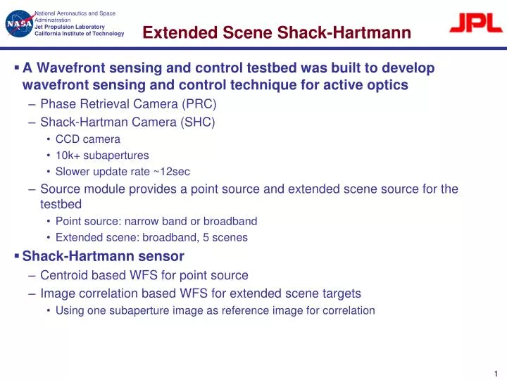
Extended Scene Shack-Hartmann. A Wavefront sensing and control testbed was built to develop wavefront sensing and control technique for active optics Phase Retrieval Camera (PRC) Shack-Hartman Camera (SHC) CCD camera 10k+ subapertures Slower update rate ~12sec

E N D
Extended Scene Shack-Hartmann • A Wavefront sensing and control testbed was built to develop wavefront sensing and control technique for active optics • Phase Retrieval Camera (PRC) • Shack-Hartman Camera (SHC) • CCD camera • 10k+ subapertures • Slower update rate ~12sec • Source module provides a point source and extended scene source for the testbed • Point source: narrow band or broadband • Extended scene: broadband, 5 scenes • Shack-Hartmann sensor • Centroid based WFS for point source • Image correlation based WFS for extended scene targets • Using one subaperture image as reference image for correlation
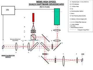
Simplified Testbed Description Optical Bench DM Accelerometers Thermal sensors Calib. Mirr. BS2 BS1 Source BS FSM DFS Source Module PRC SHC
Extended Scene #4 SHC Sub-aperture Images PRC Image (Full Aperture High Res Image • Scene #4: USAF 1951, coarse pattern, 100% contrast, negative, Groups -1 through -2 Negative of like this
ESHC Sensing Accuracy and Robustness • Using a poked DM actuator to test ESHC sensing accuracy. Plot shows the result from an actuator poking with voltages between -1 and +1 volt • Net DM poke WFE (difference between poked and flat) • ESHC measures the subaperture WF slops which then convert to OPDs. (see PRC DM setup slide) • OPD area is cropped around the actuator poke for more meaning full RMS and P-V calculations • For ESHC robustness testing the extended scene target intensity is varied from 25%, 50%, 75% and 100% to the full well exposure. RMS WFE scattering is less than 0.6 nm • DM Zygo calibration measures the gain of actuator WFE ~13.6 nm/V – matching ESHC’s measurement ESHC WFE Gain = 14 nm/V
ESHC Sensitivity • Using a small poked DM actuators to test ESHC sensitivity • 6 DM poke maps with different poke values as well as both positive and negative DM pokes – see DM actuator map and tables blow for poke actuator location and poke values • The results shown is from extended scene target #4 • The results show that ESHC can sense WFE as small as 1.4 nm P-V • DM Poke Map #1 & #2: • Act #51: DPoke = ±0.05 V = ± 7.0 nm (P-V) • Act #27: DPoke = ± 0.02 V = ± 2.8 nm (P-V) • Act #47: DPoke = ± 0.01 V = ± 1.4 nm (P-V) • Act #71: DPoke = ± 0.005 V = ± 0.7 nm (P-V) • DM Poke Map #3 & #4: • Act #51: DPoke = ± 0.1 V = ± 14 nm (P-V) • Act #27: DPoke = ± 0.04 V = ± 5.6 nm (P-V) • Act #47: DPoke = ± 0.02 V = ± 2.8 nm (P-V) • Act #71: DPoke = ± 0.01 V = ± 1.4 nm (P-V) • DM Poke Map #5 & #6: • Act #51: DPoke = ± 0.5 V = ± 70 nm (P-V) • Act #27: DPoke = ± 0.2 V = ± 28 nm (P-V) • Act #47: DPoke = ± 0.1 V = ± 14 nm (P-V) • Act #71: DPoke = ± 0.05 V = ± 7 nm (P-V) Map #1 Map #2 Map #3 Map #4 Map #5 Map #6
Compared to Point Source SHC Sensitivity • The results shown is from point source SHC • The results show that ESHC can sense WFE as small as 1.4 nm P-V • ESHC and Point Source SHC sensitivities are comparable • DM Poke Map #1 & #2: • Act #51: DPoke = ±0.05 V = ± 7.0 nm (P-V) • Act #27: DPoke = ± 0.02 V = ± 2.8 nm (P-V) • Act #47: DPoke = ± 0.01 V = ± 1.4 nm (P-V) • Act #71: DPoke = ± 0.005 V = ± 0.7 nm (P-V) • DM Poke Map #3 & #4: • Act #51: DPoke = ± 0.1 V = ± 14 nm (P-V) • Act #27: DPoke = ± 0.04 V = ± 5.6 nm (P-V) • Act #47: DPoke = ± 0.02 V = ± 2.8 nm (P-V) • Act #71: DPoke = ± 0.01 V = ± 1.4 nm (P-V) • DM Poke Map #5 & #6: • Act #51: DPoke = ± 0.5 V = ± 70 nm (P-V) • Act #27: DPoke = ± 0.2 V = ± 28 nm (P-V) • Act #47: DPoke = ± 0.1 V = ± 14 nm (P-V) • Act #71: DPoke = ± 0.05 V = ± 7 nm (P-V) Map #1 Map #2 Map #3 Map #4 Map #5 Map #6
ESHC In-Vac Repeatability Test • ESHC is repeated measuring the WFE with Spherical Mirror in • The RMS OPD variation (left plot) has shown that ESHC repeatability is less than 2.8 nm • Point source SHC shows similar repeatability ESHC Repeatability Measurement of a Static WF RMS OPD Deviation from the Mean OPD