Download
1 / 30
300 likes | 428 Views
Cryohawk. Half-scale Demonstrator of a CReSIS Polar Exploration UAV Concept Richard Colgren – KUAE Meeting 97, Aerospace Control and Guidance Systems Committee. artist’s concept. Background Intro to CReSIS KU UAV Background Sensor Payload Requirements Mission Profile Updated Design.

E N D
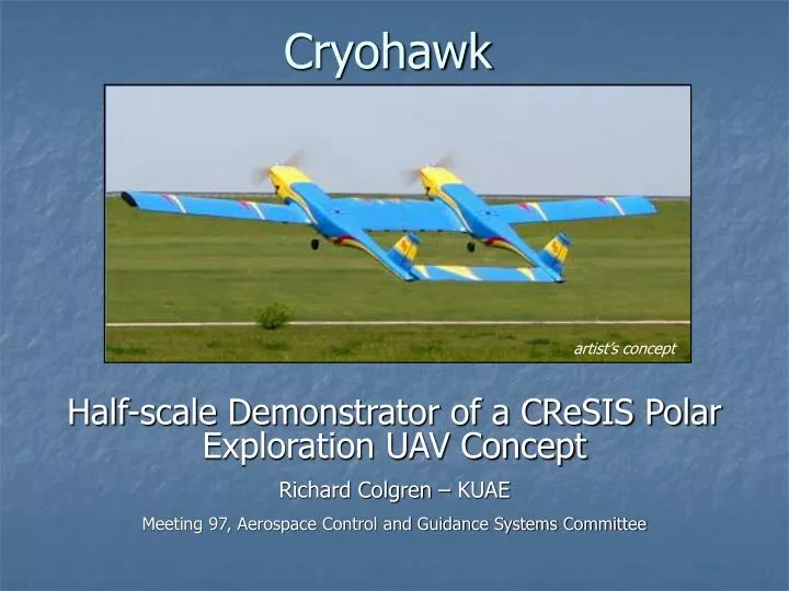
Cryohawk Half-scale Demonstrator of a CReSIS Polar Exploration UAV Concept Richard Colgren – KUAE Meeting 97, Aerospace Control and Guidance Systems Committee artist’s concept
Background Intro to CReSIS KU UAV Background Sensor Payload Requirements Mission Profile Updated Design ½ Scale Demonstrator AE 721 Student Team AE 510 Student Team PSU Team and Others Goals Current Design Challenges Roadmap
Intro to CReSIS • Science-driven technology development • Focused on mapping ice-sheet characteristics • Antarctica and Greenland missions in years 3 through 5 • Established by NSF For more info, go to cresis.ku.edu
Rotorcraft UAV Lab Objectives: Develop, test and demonstrate single and multiple Intelligent UAV concepts and systems for use in defense, scientific and commercial applications. Unmanned Aerial Vehicles Fixed Wing • - Edge 540 T High Alpha CFD/Test Program • - Hawkeye UAV Program/SAE Competition • J-3 Cub Instrumentation Project • Ultra Stick R/C Airplane Obstacle Avoidance • - Visual Based-Obstacle Avoidance Project • - NSF CReSIS Center • Phase I - Preliminary Design Developed • Phase II - GNC System Designed • Phase III - Flight Demonstrations Kansas NASA EPSCoR Program Kansas NSF EPSCoR Program Autonomous Rotorcraft Project Phase I Raptor 50 Flight Test Familiarization Phase II RMAX Flight Test Data Collection Phase III RMAX Autonomous Flight Hardware Validation Phase IV RMAX Software Validated Phase V Cooperative Flight Demonstrated Raptor 50 Leader/Follower, R-Max
KU Fixed Wing UAVs Polar UAV Hawkeye Ultra Stick 1/3 Scale J-3 Cub SAE Heavy-Lift Edge 540 T
KU Rotary Wing UAVs Yamaha RMAX and Raptor 50 Helicopters
KU Hypersonic Vehicle Studies • Generic Hypersonic Vehicle • Navy Hypersonic Vehicle Study • Supersonic Flows with Injected Streams - NASA
AST-4000 Flight Simulator Aviation Simulation Technology Inc. 14802 W. 114th Terrace Lenexa, KS 66215 USA AST-4000 Flight Simulator Specifications
KU Hypersonic Vehicle Simulation Clb Versus a & Mach Number Look-up table Original Graph MATLAB Routine (FITTER) % This routine is written in order to find the best fitting equation for [m,n]=size(A); if(n<4) % For the basic vehicle evaluation, no control surface. newA(:,1:2) = A(:,1:2) ; newA(:,3) = [0] ; newA(:,4) = A(:,3) ; A = newA ; end alpha = A(:,1) ; mach = A(:,2) ; cs = A(:,3) ; val = A(:,4) ; t = size(mach) ; cof = size(27,10) ; %%%%%%%%%%%%%%%%%%%%%%%%%%%%%%%%%%%%%%%%%%%%%%%%%%%%%%%%%%%%%%%%---1st---%%%%%%%%%%%%%%%%%%%%%%%%%%%%%%%%%%%%%%%%%%%%%%%%%%%%%%%%%%%%%%%%%%%%%%%%%%%%%%%%%%%%%%%%%%%%%%%%%% j = 1 ; X = [ones(size(val)) (alpha) (mach) (cs) ] ; % The first prediction for the aerodynamic equation con = X\val ; Cof(1:size(con),j) = con(:) ; newval = X*con ; Err = newval- val ; perf(j) = sse(Err,X) ; % The sum of squares due to error. % This statistic measures the deviation of the responses from the fitted values of the responses. % A value closer to 0 indicates a better fit. % pause %%%%%%%%%%%%%%%%%%%%%%%%%%%%%%%%%%%%%%%%%%%%%%%%%%%%%%%%%%%%%%---2nd---%%%%%%%%%%%%%%%%%%%%%%%%%%%%%%%%%%%%%%%%%%%%%%%%%%%%%%%%%%%%%%%%%%%%%%%%%%%%%%%%%%%%%%%%%%%%%%%%%% j = j+1 ; X = [ones(size(val)) (alpha) (mach) (cs) (alpha).^2 (mach).^2 (cs).^2 ] ; % The 2nd prediction for the aerodynamic equation con = X\val ; Cof(1:size(con),j) = con(:) ; newval = X*con ; Analytical Expression MATLAB Simulation FORTRAN Simulation
UAV Sensor Payload • Depth-sounding radar • Surface-scanning lidar • Other sensors artist’s concept Ice Sheet Bedrock
UAV Sensor Payload • Depth-sounding radar • Surface-scanning lidar • Other sensors Ice Sheet Radar Bedrock
UAV Sensor Payload • Depth-sounding radar • Surface-scanning lidar • Other sensors Lidar Ice Sheet Radar Bedrock
UAV Requirements • 175 lb payload • Radar antenna array (14 ft by 2.5 ft) • 6,000 km (3,200 nm) round trip • 1 km (3,300 ft) AGL for survey • 126 knots for survey (155 knots cruise) • Jet or Diesel fuel preferred
Mission Profile (Greenland) • Taxi / takeoff / climb • Cruise 200 nm to glacier • Conduct survey • Local survey or • Regional survey • Return cruise to base • Land / taxi
Mission 1 Profile (Antarctica) • Taxi / takeoff / climb • Cruise 1,350 nm • Conduct survey • Local survey or • Regional survey • Return cruise • Land / taxi
Low wing Larger center wing More details Antennas, etc. Redesign – Full Scale Concept artist’s concept
Full Scale Sizing Design Point
Revised Design • Take-off gross weight 2,806 lbs • Empty weight 1,552 lbs • Fuel weight 1,064 lbs
Regression Study of 18 UAVs Design
Engine Power Estimation • Wing loading = 22 lb/ft2 • Power loading = 19 lb/hp • Total Power Required = 2806/19 150 hp • Power Required per engine = 75 hp • ½ Scale to use two 3W-75 engines
Graduate Design-Build-Fly Team • Four students: • David Borys • Satish Chilakala • Edmond Leong • Nelson Brown • Advisors: • Dr. Richard Colgren • Jewon Lee (TA)
Collaboration • Undergrad manufacturing class (AE510) • Center wing • Pittsburg State University • Water-jet cutting • Templates • Kansas State University • Autopilot • You?
Goals • Stability and control demonstrator for CReSIS • Experience for KUAE • Manufacturing larger aircraft • Operating sizable UAVs • Asset for ongoing UAV research
Schedule • October 11th PDR and Scaled Design • October 25th Begin Engine Testing • November 3rd CDR (Full Size and Scaled) • November 21st Start Construction • December 1st Final Presentation • December 5th Initial Flight Test Plan • December 15th Final Report Submission • January 20th All Scaled UAV Parts • May 15th First Flight
Current Scaled Design • 90 lb (empty) • 18 ft span, 9 ft long • Main spar 1.75” dia., 1/8” thick, 6061-T6 aluminum tube • Wings • Fiberglass skin • Balsa & Foam ribs • Fuselage • Fiberglass skin • Wooden structure
Challenges • Time • Partnerships with: • Undergraduate class • PSU • KSU • Embry-Riddle • Others? • Money • Seeking support from: • University of Kansas ($2,000) • CReSIS ($8,000) • Others?
Questions / Discussion artist’s concept artist’s concept