Download
1 / 16
170 likes | 326 Views
Different options for the assimilation of GPS Radio Occultation data within GSI. Lidia Cucurull NOAA/NWS/NCEP/EMC. GSI workshop, Boulder CO, 28 June 2011. Outline. Introduction to GPS Radio Occultation Default (operational) configuration in GSI Recent additional capabilities Outlook.

E N D
Different options for the assimilation of GPS Radio Occultation data within GSI Lidia Cucurull NOAA/NWS/NCEP/EMC GSI workshop, Boulder CO, 28 June 2011
Outline • Introduction to GPS Radio Occultation • Default (operational) configuration in GSI • Recent additional capabilities • Outlook
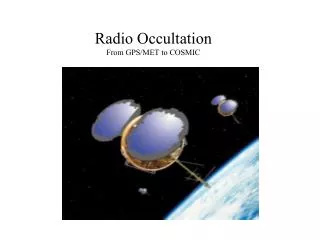
Occulting GPS Ionosphere Neutral atmosphere LEO Earth Radio Occultation concept • An occultation occurs when a GPS (GNSS) satellite rises or sets across the limb wrt to a LEO satellite. • A ray passing through the atmosphere is refracted due to the vertical gradient of refractivity (density). • During an occultation (~ 3min) the ray path slices through the atmosphere Raw measurement: change of the delay (phase) of the signal path between the GPS and LEO during the occultation. (It includes the effect of the atmosphere). GPS transmits at two different frequencies: ~1.6 GHz (L1) and ~1.3 GHz (L2).
what do we “want” to assimilate? Raw measurements of phase of the two signals (L1 and L2) s1, s2, Bending angles of L1 and L2 a1, a2 (neutral) bending angle Clocks correction, orbits determination, geometric delay Refractivity a Atmospheric products Ionospheric correction N Abel transfrom T, Pw, P Hydrostatic equilibrium, eq of state, apriori information
Choice of observation operators L1, L2 phase L1, L2 bending angle Neutral atmosphere bending angle (ray-tracing) Linearized nonlocal observation operator (distribution around TP) Local refractivity, Local bending angle (single value at TP) Retrieved T, q, and P Not practical Possible choices Complexity Not good enough
Forward Operator for refractivity (default) • (1) Geometric height of observation is converted to geopotential height. • (2) Observation is located between two model levels. • (3) Model variables of pressure, (virtual) temperature and specific humidity are interpolated to observation location. • (4) The hypsometric equation is used to compute the pressure at the observation location. • (5) Model refractivity is computed from the interpolated values. • The assimilation algorithm produces increments of • surface pressure • water vapor of levels surrounding the observation • (virtual) temperature of levels surrounding the observation and all levels below the observation (ie. an observation is allowed to modify its position in the vertical in the outer loop)
Forward Operator for refractivity (con’td) • Each observation is treated independently and we account for the drift of the tangent point within a profile - GPS RO derived soundings of refractivity are not vertical due to different angular velocities between the GPS and LEO satellites. • Quality control procedures are based on two different seasons (summer and winter). • Optimal observation error characterization is estimated following Desroziers (2005). • Observations are assimilated up to 30 km in the operational and default configurations - QC and observation error have not been tuned above this height. • User will need to tune QC and observation errors in order to assimilate higher observations and/or if GSI is being used with a model different from GFS or NAM. • Detailed description of the changes and results can be found in Cucurull 2010, WAF, 25,2,769-787
Additional capabilities • A forward operator to assimilate bending angle observations (a rawer product than refractivity) has been developed, implemented and tested at NCEP. Quality control procedures and observation error characterization have been tuned accordingly. • An earlier version of this forward operator was available at NCEP in 2006 (Cucurull et al. 2007, Cucurull et al. 2008). The updated bending angle code has many improvements over the earlier version. • The bending angle code enables the assimilation of GPS RO observations up to 50 km – QC procedures and observation error structures have been tuned up to this height. • QC and observation errors have been tuned similarly to refractivity. • The drift of the tangent point is taken into account.
Additional capabilities (cont’d) • Algorithms to include the compressibility factors in the computation of the geopotential heights have been implemented in GSI to compute a more accurate forward operator for GPS RO. • Both refractivity and bending angle codes have the option to use the compressibility factors. • When the compressibility factors are used, the GPS RO forward operators use a more accurate set of refractive indices. • The use of compressibility factors will affect the assimilation of GPS RO observations as well as all the observations that use geopotential heights. In fact, any subroutine within GSI that makes use of the geopotential heights will be affected by the changes.
Forward Model for bending angle • Make-up of the integral: • Change of variable to avoid the singularity • Choose an equally spaced grid to evaluate the integral by applying the trapezoid rule
Experiments to test bending angle • Period: 2 February 2011 – 22 March 2011 • PRREF: current operational model – assimilation of refractivities up to 30 km. • PRBNDZ: experiment – assimilation of bending angles up to 50 km & use of compressibility factors & updated refractive indices. • Both experiments use the current GFS model
Outlook • Assimilation of GPS RO observations using the bending angle code with the compressibility factors is currently being tested with the hybrid GSI system and it is expected to be operational in 2012. • Future work will focus on the following issues: • Better use of the observations in the lower troposphere and upper stratosphere. • Further understanding of the GPS RO impact on moisture. • Analysis of the sensitivity of the forward operator to additional terms. • Design and implementation of more accurate forward operators (along with updated quality control procedures and observation error structures).