Download
1 / 31
310 likes | 474 Views
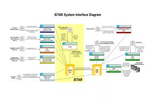
EOS at SPPS. Adrian L Cavalieri, David M Fritz, SooHeyong Lee, Philip H Bucksbaum, David A Reis (FOCUS Center, University of Michigan) Holger Schlarb ( DESY ) Patrick Krejcik, Jerome Hastings ( SLAC/SSRL ). 50 ps. SLAC Linac. RTL. SPPS. 9 ps. 0.4 ps. 1 GeV. 20-50 GeV. <100 fs. 3km.

E N D
EOS at SPPS Adrian L Cavalieri, David M Fritz, SooHeyong Lee, Philip H Bucksbaum, David A Reis (FOCUS Center, University of Michigan) Holger Schlarb (DESY) Patrick Krejcik, Jerome Hastings (SLAC/SSRL)
50 ps SLAC Linac RTL SPPS 9 ps 0.4 ps 1 GeV 20-50 GeV <100 fs 3km Timing for Ultrafast X-ray Science • SPPS is an R&D facility for the Linac Coherent Light Source (LCLS) and is a test bed for future beam diagnostics • Electron bunches at SPPS are as short as 80fs FWHM, comparable to the bunches that will drive future XFELs • EOS delivers shot-to-shot bunch length to machine operators • 2m undulator after bunch compression delivers 80fs FWHM hard x-ray pulses • EOS delivers shot-to-shot arrival time to users
EOS and “Pump-Probe” • Typical time resolved experiment utilizes intrinsic synchronization between pump excitation and probe system response impulse time • Electro-Optic Sampling (EOS) delivers arrival time to users • Pump-Probe experiments now possible at XFELs • Machine jitter exploited to sample time-dependent phenomena
Geography EOS undulator EOS timing applicable IF optical path lengths remain constant amp X osc
Electro-Optic Sampling • Crystal is affected by applied DC electric field • Principle axes of crystal system are modified • Index of refraction along these axes changes • Probe laser field is decomposed in primed coordinate system • Phase shift between components can be detected
Electric Field of 30GeV Electron Bunch • Approximate field assuming: • Steady-state • Accurate calculation requires numerical analysis • Crystal is in a 6” 6-way vacuum cross so approximation is good 3.4nC
Spatially Resolved Electro-Optic Sampling (EOS) • Spatially resolved EOS can deliver measurements with high enough resolution to capture electron bunches at SPPS • technique pioneered using table-top systems by Heinz et. al. in 2000 • spectrally resolved EOS cannot be used due to fundamental bandwidth limitation • Resolution limit of technique dominated by EO crystal thickness Laser probe later relative to electron bunch Laser probe earlier relative to electron bunch EO Crystal
Spatially Resolved EOS (long bunch) EO Crystal
Spatially Resolved EOS time polarizing beamsplitter integrated intensity time; space time integrated intensity Arrival time and duration of bunch is encoded on profile of laser beam
SPPS Facility LINAC Accelerator Tunnel Laser Room & X-ray Hutch
Effect of Long Pulse Probe Laser • Probe pulse longer than e-bunch • EO signal will be broadened • If probe pulse shape is very well known, we should be able to deconvolve e-bunch shape • Signal to background problems introduced • Probe pulse uncompressed (~10’s of picoseconds or longer) • Measurement will yield no spatially dependent signal
SLM640-pixel Pulse Shaper • 640-pixel SLM can introduce arbitrary dispersion • Genetic Algorithm used to find configuration that minimizes total transport dispersion • frequency doubled throughput provides feedback • nearly transform limited pulse delivered when combined with grating pair to compensate for GVD
Ultrafast Laser Transport: 3rd Order Correction • Data taken with a 110m spool of test fiber at UofM with 128-pixel SLM • Spectral width of transmitted pulse is ~10nm Without Pulse Shaper With Pulse Shaper FWHM 600fs FWHM 160fs
135fs (FWHM) Transport Results • Autocorrelation used for measurement of laser pulse arriving at EO chamber • Find pulse is not transform limited • Improvement can be made in chromatic aberration in pulse shaper • Fixed phase mask can be used to increase capacity of pulse shaper Schematic PMT BBO
Spatially Resolved EOS Data time polarizing beamsplitter integrated intensity time; space time integrated intensity
Single-Shot Data acquired with ZnTe Single-Shot w/ high frequency filtering Timing Jitter Data (20 Successive Shots) iCCD counts shot time (ps) color representation time (ps)
Effect of accelerator parameters on EO signal:Observation of resolution limit • Changing Linac Phase detunes electron bunch compressor
Estimate Frequency Response Cut-Off EO crystal sign of effect accumulated effect
EO crystal imaging fiber couple • EO signal/feature small ~50um extent • Vacuum ports and other optics reduce angular resolution • Object does not lie in a plane perpendicular to optical axis • High resolution is required over a large depth of field (for adequate single-shot window)
Effect of Poor Imaging on Single-Shot Data poor imaging • Broadening also due to insufficient resolution in imaging system • 100fs feature corresponds to a 30um feature in the beam • Current chamber limits achievable resolution • Broadening is still due predominantly to crystal thickness and cut-off frequency reference
Imaging Solution • Depth of field fixed by single-shot window • Rate of time-sweep fixed by incident angle • Resolution requirement of imaging system fixed by incident angle
New EO Chamber • Accepts 15, 30, and 45 degree angle of incidence • Thick and thin crystal on actuator, user chooses which crystal is used for the EOS • No internal optics • Shorter path length to exit port (use shorter focal length imaging optics)
The Flowchart E-beam/X-rays RF Pump Laser (Experiment) EOS
Optical Path Length Jitter • Long term thermal drift caused by: • Optical fiber transport • RF reference cable • Short term drift caused by vibration • Feedback used to stabilize fiber length and keep signal in single shot window • Tracking changes made in optical path to keep timing information valid
EO/Streak Camera Correlation(no fiber stabilization) A. MacPhee, LBL • 5000 shots recorded at 10Hz rate • EO arrival time accuracy: <30fs • Streak Camera arrival time accuracy: ~150fs • Correlation between measurements is .707
EO/Melting Correlation(no fiber stabilization) • 30 shots recorded at 1Hz rate • EO arrival time accuracy: <30fs • Melting arrival time accuracy: ~50fs • Agreement between two measurements is 60fs RMS
Is the measurement plausible? Red line: bunch charge distribution • sum of two gaussians, one with 100% amplitude, 80fs width; the other 20% amplitude, 1ps width • Instrument function estimated to be gaussian - 200fs width • combine laser pusle duration with imaging imperfections • returns narrow feature in data • Blue line is the convolution of the two – corresponds to expected EO signal Expected EO signal K. Gaffney time (fs)
Is this measurement plausible? • Good agreement between test function and the experimental data • Instrument function – reasonable estimate that returns the sharp central feature • Choice for charge distribution convolved with instrument function matches data, but does not match simulation Single-shot data w/ convolution function Red line: real single-shot data Blue line: convolution function
Synchronization Using RF Reference 170 fs rms