Download
1 / 42
420 likes | 580 Views
Sponsor & Organization: Professor Larry Bernstein SSW 540 Fundamentals of Software Engineering Stevens Institute of Technology School of Systems Engineering & Engineering Management Castle Point on Hudson Hoboken, NJ 07030. Ground Controller Project. Overview. Project Value

E N D
Sponsor & Organization: Professor Larry Bernstein SSW 540 Fundamentals of Software Engineering Stevens Institute of Technology School of Systems Engineering & Engineering Management Castle Point on Hudson Hoboken, NJ 07030 Ground Controller Project
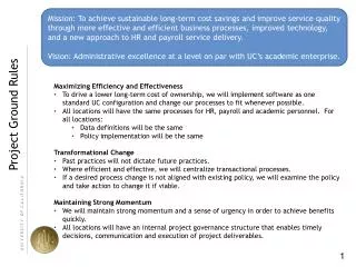
Overview Project Value • The Ground Controller will identify, track, and predict the impact location of a Space Capsule during its re-entry process to ensure prompt recovery. Project Description • The Ground Controller operates as a tracking computer for the re-entry of a Space Capsule. • It consists of one ground-based radar unit for surveillance and capsule detection, tracking, and impact projection. • It also has a Communications Relay Group for communications support to other systems that need capsule location and impact prediction. • An Information Coordination Center controls the Ground Controller and coordinates its operation with other controllers and higher level Space Command Authorities. • The Ground Controller has a Control Computer, which is responsible for performing the tracking, impact projection, as well as other of the system’s major command and control functions. • The Ground Controller will execute impact predictions when the Space Capsule descends from 400,000 feet to 100,000 feet, and a new projection will be computed every ten (10) seconds. • Recovery ships are deployed based on the Ground Controller’s predictions and they will use their splash detection radar systems to confirm impact.
Overview – Cont. Project Constraints • The Ground Controller uses equipment originally designed for the Patriot System that protected against Iraqi Scuds. • The Control Computer used is based on a 1970s design with relatively limited capability to perform high precision calculations: It cannot compute roots of a function nor invert a matrix. Integration can only be approximated with finite difference equations, therefore polynomial filters are used for tracking and surface impact projection. • The Ground Controller will execute impact predictions when the Space Capsule descends from 400,000 feet to 100,000 feet, and a new projection will be computed every ten (10) seconds. The last six (6) projections are used to smooth the results, so that there is a new projection provided at least every minute. • The system will use a range-gate algorithm to identify and track the Space Capsule. If the range-gate finds an object within the calculated range-gate area, it confirms that it is a Space Capsule. The range-gate provides a prediction of where the capsule will next appear as a function of the known velocity and time of the last radar detection. • To predict where the Space Capsule’s trajectory; time, velocity, and gravity are expressed as real numbers. Velocity is expressed as a whole number and a decimal. Time is kept continuously by the system’s internal clock in tenths of seconds, but is expressed as an integer. Project Directions • The Ground Controller is part of an infrastructure of many Ground Controllers used to identify, predict, and track Space Capsule re-entry and impact location. The Ground Controller interacts with an Information Control Center to coordinate with other controllers and other higher level Space Command Authorities.
Measurable Operational Value (MOV) • The Ground Controller will improve Space Capsule impact location predictions by 90% and increase recovery time by 50%. • The Ground Controller is designed to be a stand-alone unit. • For the intended purpose, it is mounted to a ship, although it is quite versatile and may be mounted on any sort of platform. • It has a well designed interface and allows for optimal interaction from a human operator. • The Ground Controller interacts with an Information Control Center, which also communicates with network of Ground Controllers and other higher level Space Command Authorities. This ensures prompt deployment of recovery ships to the projected Space Capsule impact location.
Project Management & Organization Structure • We have eight people on our team. Every member has been assigned a role on the project based on their area of expertise. • The team meets at least once a week (more often when necessary) and communicates virtually between meetings. • Team Member Roles & Responsibility: • Pedro H Curiel – Program Manager / Architect • Amber Gell – Systems Engineer • Jerrod Magoon – Systems Engineer • Wayne Haufler – Software Engineer / Architect • Tim Fisher – Analyst • Byron Prelow – Certified Test Conductor/Test Planning Coordinate Drafter/Pro-E • Khoa Nguyen – Configuration Management Manager • Anh Dang – Configuration Management Manager
GBR system tracking capsule ISS Radar Range Capsule Range Gate Range gate tracking (every 10 sec) Capsule projected path Range gate tracking (every 10 sec) & Impact Prediction (every 1 min) 400 Kft 5 degree re-entry angle 100 Kft GBR 0 ft
Use Case Scenarios Use Case 1: Scan for capsule Brief Description: Scan area specified by ICC for capsule re-entry. GC ship is deployed to approximate location Actors: internal: GC Operator, Control Computer (CC), Ground Based Radar (GBR) and a Communications Relay Group (CRG) external: Information Control Center (ICC) Trigger: Radar detects object within range Preconditions: • GBR has been restarted just before mission starts • Radar is charged • Sea ship providing adequate power • ICC online Nominal: Start Radar scanning. Detect potential target base on strength of return signal. Off-nominal: • Computer shuts down – go with backup • Radar detects more then one target – Ignore other objects and only track capsule. Post-conditions: Detect enabled and system sets up an analysis of the object. Data is collected and time log book is recorded. Use Case 2: Detect capsule Brief Description: The GC determines if the object detected is in fact the space capsule analyzing the objects features. Actors: internal: GC Operator, Control Computer (CC), Ground Based Radar (GBR) and a Communications Relay Group (CRG) external: Information Control Center (ICC) Trigger: Radar sends characteristics info of object detected to CC Preconditions: • Computer is up and running properly • Sea ship provides adequate power • GC operator is present • Target appears in the distance Nominal: After an object is detected the system analyzes it for qualities (its speed, size, etc.) After analysis its determined if it matches the capsule characteristics stored in memory. ICC is notified of object detection. Off-nominal: • Object is determined to not be capsule – continue with another scan • Object cannot be determined – operator makes the necessary decision consulting with ICC Post-conditions: GC determines incoming object is capsule and system is prepared to activate “range gate” to anticipate next capsule location and continue tracking. Data is collected.
Use Case 3: Track capsule location Brief Description: By using the “range gate “within the GC radar an area in the air space is calculated on where the system should look next for the capsule. By analyzing the capsule known velocity and time the range gate predict where the capsule will appear next. Actors: internal: GC Operator, Control Computer (CC), Ground Based Radar (GBR) and a Communications Relay Group (CRG) external: Information Control Center (ICC), space capsule Trigger: Incoming object is verified as capsule Preconditions: • Computer is up and running properly • Sea ship providing adequate power • Operator is present • Target is identified as capsule Nominal: Computer analyzes incoming capsule and determines its velocity and the time of last radar detection. Both time and velocity are expressed as real number. The range gate filters out info about airborne objects outside its calculated area and only process the information needed to track capsule. The range gate area is predicted to continue tracking and logging data. Off-nominal: • System failure – velocity and time cannot be calculated • The predicted location is clearly off - operator makes necessary adjustments Post-conditions: Range gate performs calculation and anticipates location every 10 seconds. Data is collected Use Case 4: Calculate capsule impact location Brief Description: After the range gate has been logging position data since detection and capsule has reached descent range between 400 to 100 kft computer will start calculating impact locations once every minute with the last 6 range gate location predictions. Actors: internal: GC Operator, Control Computer (CC), Ground Based Radar (GBR) and a Communications Relay Group (CRG) external: Information Control Center (ICC), space capsule Trigger: Range gate has confirmed capsule location within 400 to 100 kft of surface Preconditions: • ICC communications online • GC Operator is present • Access to past range gate calculations Nominal: Impact locations are calculated once every minute by using the last 6 location points. Impact location calculation is communicated to ICC Off-nominal: • System failure – go with backup • Tracking is off - the operator makes the necessary adjustments • Last minute confirmation of object being tracked is not capsule – communicate with ICC Post-conditions: Capsule impact location is adequately predicted and communicated to ICC every minute when capsule is between 400 to 100 kft of landing. ICC deploys recovery ship and confirms capsule location. Data is collected.
Use Case 5: Collect data for post mission analysis Brief Description: After the process is complete all the data is collected for the mission. It is analyzed for any problems or concerns. Any changes are made and the operator and engineer are informed of them. A time log is kept for every step of the mission. Actors: internal: GC Operator, Control Computer (CC), Ground Based Radar (GBR) and a Communications Relay Group (CRG) external: Information Control Center (ICC), Trigger: Capsule has been recovered Preconditions: • A time log has been completed every step of the mission • A large amount of data has been collect to be analyzed • Computer system ready for analysis is up and running Nominal: After the mission is complete the analyst obtains all the necessary data to do is analysis of the mission. The operator informs the analyst of any problems to look for and any changes that may have to be made. The analyst looks at the data to develop an analysis report. Any problems or discrepancies are reported to the operator and engineer to make the necessary changes on the GC. Off-nominal: • Not all times are recorded for the mission – estimates are made and fault is corrected • System failure – go to backup Post-conditions: Any problems are reported and necessary changes are made to the GC after the analysis. Also, accuracy of the impact location is recorded. System is shut down.
Process View Scan (GBR) - Radar pulses to locate capsule Detection & Identify - Reflected pulse is compared to make sure its capsule Tracking & Verify (Range gate) - calculation for next position prediction and verify its capsule • Communication (CRG) • Let know ICC latest impact prediction Projection - Use last 6 tracking points for an impact prediction every minute Database - To save impactpredictions 1 per minute ROM - Characteristics of space capsule Database - To save once every 10 second sampling
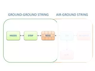
Logical ViewPhysical View w/o Processes ICC GCGround Control CRGComm Relay Group GBRGround Based Radar CCControl Computer RGRange Gate
Logical Viewwith SW Objects in Pipeline Architecture ICC GCGround Control CRGComm Relay Group GBRGround Based Radar Comm RGRange Gate CCControl Computer Comm Scan Scan CRG_Rep RG_Rep CC_Rep PulseCmds Radar_Rep Tracking UI Position_Predictionsevery 10 secs Projection Tracking Identify Tracking Detection Impact_Predictions every 60 secs Range _Gate Signal _Gate Altitude _Gate Blip
Logical Viewwith Stored Arrays ICC GCGround Control CRGComm Relay Group GBRGround Based Radar Comm RGRange Gate CCControl Computer Comm Scan Scan CRG_Rep RG_Rep CC_Rep PulseCmds Radar_Rep Tracking UI Position_Predictions every 10 secs Projection Tracking Identify Tracking Detection Impact_Predictions every 60 secs Range _Gate Signal _Gate Altitude _Gate Blip Range _Gates Reference_Signal Blips Last 6 Blips
Logical View with Exec for Querying Stored Arrays, Setting Parms ICC GCGround Control CRGComm Relay Group GBRGround Based Radar Comm RGRange Gate CCControl Computer Comm Scan Scan CRG_Rep RG_Rep CC_Rep PulseCmds Radar_Rep Tracking UI Position_Predictionsevery 10 secs Exec Projection Tracking Identify Tracking Detection Impact_Predictions every 60 secs Range _Gate Signal _Gate Altitude _Gate Blip Range _Gates Reference_Signal Blips Last 6 Blips
Logical View with Exec for nonPipelined, Centralized Arch ICC GCGround Control CRGComm Relay Group GBRGround Based Radar Comm RGRange Gate CC Control Computer CRG_Rep RG_Rep CC_Rep PulseCmds Radar_Rep Position_Predictionsevery 10 secs Exec UI Projection Impact_Predictions every 60 secs Range _Gate Signal _Gate Altitude _Gate Blip Range _Gates Reference_Signal Blips Last 6 Blips
Physical View GC Box • GC is Composed of • Control Computer (CC), • Ground Based Radar (GBR) • which includes the Range Gage (RG) computer and a • Communications Relay Group (CRG) to communicate with the Information Control Center (ICC). GBR Box Range Gate Tracking & Verify Scan (GBR) CC Box Detection & Identify Projection Communication to ICC (CRG) Capsule Characteristics ROM Capsule Position Database Capsule Impact Prediction Database
Statement of Software Requirements • Caveat: Lacking knowledge of the existing legacy software architecture, this set of software requirements necessarily assumes or imposes an architecture on top of or in partial replacement of the existing legacy architecture. This approach is likely to result in incompatible architecture match and/or minimal software reuse. A few objects are noted with “(wrapper around existing code)” where it seems that might work. • … • RG’s Blip object • Blip object’s “new” method, when invoked, shall send a message to the Blips object (Note: Blips object different from Blip object), appending a Blip record with timestamp to an ever-growing chronological record. • Blip object’s “new” method, when invoked, shall send a copy of itself (Blip record) to the Altitude_Gate object, the next object in the pipeline. • RG’s Altitude_Gate object • The Altitude_Gate object shall receive a Blip object. • The Altitude_Gate object shall compute the capsule’s altitude from data in the Blip. • The Altitude_Gate object shall flag the Blip object as being “TrackingBracking” when altitude is between 400,000 feet and 100,000 feet. • The Altitude_Gate object shall send the Blip object to the SignatGate. • …
Statement of Software Requirements • WARNING: If each arrow is implemented by invoking (calling) the destination object’s method by the source object, then the circuit path of arrows within RG would result in something like a “Circular Call Reference Error”. These should be implemented with a nonblocking message passing mechanism.… • RG’s Blip object • In Blip object’s “new” method, • Call Blips object’s Store method (Note: Blips object different from Blip object), • which pushes the Blip record with timestamp to a limited stack data structure, an ever-growing chronological record. • Call Altitude_Gate’s Check method with a copy of the Blip record • RG’s Altitude_Gate object • In Altitude_Gate object’s Check method, • Receive Blip data record • Check inputted Blip data for validity • if Valid_data is True • Call computeAltitude to do that from data in the Blip. • sin A = a / c = Alt/Range; Alt = Range * sin 5 degrees • Blip.Tracking = False • if Alt <= 400,000 ft AND Alt >= 100,000 ft • Blip.Tracking = True • (where Blip.Tracking is a boolean field called Tracking in the Blip record) • Call Signal_Gate’s Check method with the Blip data record.
Development View Tracking & Verify (Range Gate) ICC Communication (CRG) Scan (GBR) Detection & Identify Projection Presentation Layer Presentation Layer Presentation Layer Presentation Layer Presentation Layer GUI GUI GUI GUI GUI Physics Layer Physics Layer Physics Layer Physics Layer Algorithm Components Algorithm Components Algorithm Components Algorithm Components Data Layer Data Layer Data Layer Data Layer Data Access Layer Components Data Access Layer Components Data Access Layer Components Data Access Layer Components
Development View - Data Capsule Characteristics ROM Capsule Position Database Capsule Impact Prediction Database Table Schema Stored Procedures Table Schema Stored Procedures Table Schema Stored Capsule Characteristics Stored Capsule Location Log Stored Capsule Impact Prediction Log Reference_Signature Re-Entry Angle or Elevation Velocity Expected Parametric “Shape” of Signal Envelope Capsule Position or ‘Blip’ TimeStamp Predicted Signature Box: Azimuth_Left Azimuth_Right Elevation_Top Elevation_Bottom Range Impact_Prediction TimeStamp of Impact Range (relative to radar) Expected Iimpact Oval: Focal_x, Focal_y SemiMajorAxis SemiMinorAxis
Development Schedule and Gantt Chart • COCOMO method was used for schedule estimations • 16 Unadjusted Function Points • Assumption of using the C programming language • Total Lines of Code (LOC) = 1664 • Applying the 1.664 KLOC to the Effort equation • Assuming we have Embedded Software • Effort = 6.63 Staff Months • Due to the fact that we are students, working professionals in separate fields, have families and are involved in other social activities. We estimated that each of us can spend 8 hours per week.
At 8 hours/week/student • 1 Staff Week = 40 hours = 5 Student Weeks • Since there are generally 4 weeks in a month • 1 Student Month = 4 x 5 Student Weeks = 20 Student Weeks • In general, 20 weeks = 5 months • Therefore, 1 Student Month = 5 Staff Months • Once this was found, we applied to our Effort equation: • Student Months = 5 x 6.63 Staff Months = 33.16 • Our team is made up of eight people: • 33.16 Student Months / 8 Students = 4.15 Months • Therefore, we estimate that this project can be completed within 5 months of the start date.
Test Plan Cooperative Testing • Chosen as first test to be performed by our team. • Fosters cooperation amongst subsystem designers. • Use of test beds which were provided by the original system testers. • Helps to eliminate problems before software is seen by external test team.
Unit Testing • Allows us to test each module/use case individually • Scan (scan for capsule) • Detection & identify (detect capsule) • Tracking & verify (track capsule location) • Projections (calculate capsule impact location) • Communication (collect data for post-mission analysis) • All test data and Test results will be kept with the module’s source code.
Stress & Regression Testing • Stress Testing • Test software detection mode up to 800,000 ft to analyze behavior. • Test impact predictions/projections beyond 100,000 ft – 400,000 ft range. • Allows us to see how software will behave under “abnormal” operating conditions • Regression Testing • Ensure original software features still function the same with changes. • Use test cases from original software on current versions • Inform team of any problems existing due to changes in software. • Inform team if software ran correctly.
System/Integration Testing • Testing connections between the following: • ICC to CC system • CC system to RG • RG to GC. • GC to RG • RG to CC system • CC system to ICC
Configuration Management Deliverable Items • All Acquisition, Design, Development, Production, Operation, Support and Maintenance Decision Making: • Requirements Traceability Matrix (RTM, DOORS, CRADLE, CORE, etc.) • Software Development Plan (SDP) • Software Standards & Procedure Manual (SSPM) • Software Requirements Specifications (SRS) • Interface Design Document / Interface Requirements Specification (IDD / IRS) • Software Development Files (SDF) • Software Requirements Trace Matrix (SRTM)/Software Requirements Verification Matrix (SRVM) • Software Test Documents, SW Test Plans, SW Test Reports (STD, STP, STR) • Software Design Documents (SDD) • Software (including all interfaces, simulators, emulators, drivers, etc.) • Government Provided Software(GPC) • 3rd Party Code/ Contractor Supplied Software (CSS) • (i.e; developed by universities, research labs, etc.) • SW Environment (Compliers, linkers, GUI builders, CASE tools, project planning tools, CM Tools, debuggers, SW Licenses and maintenance) • Commercial Off-the-Shelf (COTS) Software, Free & Open Source Software (FOSS) • Software Version Description / Software Product Specification (SVD / SPS) • Government Furnished Information (GFI) • All Contract Data Requirements Lists/ Supplier Data Requirement Lists (CDRLs/SDRLs) • “Official” deliverable items must be delivered from CM.
Configuration Management FCA - Functional Configuration Audit PCA - Physical Configuration Audit RFP – Request for Proposal CSCI – Computer Software Configuration Item HWCI – Hardware Configuration Item
Coding Standard • NASA SOFTWARE CODING STANDARD GUIDES: • To assure high quality, reliability and safety, the following NASA Software Coding Standard will be used as guide for coding practices: • NASA- JSC27209: C Coding Standard for the Orbiter Interface Unit (OIU) Project. • NASA-JSC ISS SIGI Attitude Processor: C Coding Style Guide • NASA-JSC C Coding Standard for the X-38/V201 GN&C Flight Software • Dynamic memory allocation (e.g., use of functions calloc() and malloc()) shall[42] not be used, in order to reduce the risk of memory leaks and promote a fixed memory model. • Module execution rate shall[72] not be assumed to be a constant unless it is running in a deterministic, real-time system. • Header files shall[81] not be nested • Concurrent programming shall[83] not be used
NASA Standards & Processes The software development life cycles shall compliance with the following Standards and Processes: NASA-STD-0005 NASA Configuration Management (CM) Standard NPD 2820.1 NASA Software Policies NPR 1441.1 NASA Records Retention Schedules NPR 7120.5 NASA Program and Project Management Processes and Requirements NPR 7150.2 NASA Software Engineering Requirements NASA-STD-8719.13 Software Safety Standard NASA-STD-2202-93 Software Formal Inspections Standard NASA-GB-8719.13 NASA Software Safety Guidebook NASA-GB-A201 Software Assurance Guidebook, September 1989 NASA-GB-A301 Software Quality Assurance Audits Guidebook, December 1990 NASA-GB-A302 Software Formal Inspections Guidebook, August 1993 IEEE 730-2002 IEEE Standard for Software Quality Assurance Plans ISO/IEC 12207:1995 Software life cycle processes ISO 90003:2000 Quality Management And Quality Assurance Standards – Part 3: Guidelines For The Application of ANSI/ISO/ASQC 9001:1994 To The Development, Supply, Installation And Maintenance Of Computer Software ISO 10007:2003 Quality management systems - Guidelines for configuration management IEEE 982.1-1988 IEEE Standard Dictionary of Measures to Produce Reliable Software IEEE 1012-1998 IEEE Standard for Software Verification and Validation IEEE Std. 1028-1997 IEEE Standard for Software Reviews IEEE Std. 828-1998 IEEE Standard for Software Configuration Management Plans ANSI/EIA-649-1998 National Consensus Standard for Configuration Management EIA-649-A 2004 National Consensus Standard for Configuration Management GEIA Standard 836-2002 Configuration Management Data Exchange and Interoperability
Build Plan Experience indicates that a typical thread requires about three months completely integrating and testing.
Physics-Related Questions • Given that “the control computer used is based on a 1970s designed with relatively limited capability to perform high precision calculations”, there is a concern that the computer AND the radar might not be able to handle the much larger numbers and distances involved in this capsule-tracking problem compared to a relatively local missile tracking problem. • What is the Range of the Radar? • Answer: http://www.army-technology.com/projects/patriot/ • The radar system has a range of up to 100km. • What is the expected straight line Range of a capsule when it is some 400KFT altitude uprange from its ballistic impact point (where current capsule velocity vector intercept s the earths surface), given an expected 5 degree reentry angle? • Would this Range distance put the capsule beyond the horizon? • Given a silly simplifying assumption of a flat earth, trigonometrically, sin A = a / c = Alt/Range; Range = Alt/sinA = 400K / sin 5 degrees = 4,589,485 ft = 4,600 KFT = * 0.3048 m/ft = 1,398 km cos A = b/c = ground range / beam range; gnd range = cos A * beam range= cos 5 * 4,589,485 ft = 4,572,020.9 ft • Is expected max range within max radar range? No, 1,400 km > 100 km • Is expected max range representable within available floating point data type, • Max unsigned integer representable is 2^24 - 1 = 16,777,216 -1 = Hex 100 0000 – 1 = FF FFFF • but what would be the maximum representable Floating Point in 24 bit word? • Is a 48 bit double precision available?
Radar Range Too Short ISS Capsule Local Horizontal Radar Range Range Gate Range gate tracking (every 10 sec) Capsule projected path 5 degree re-entry angle 1,400 KM 400 Kft 100 KM Radar Max Range 100 Kft GBR 5 degree re-entry angle 0 ft
HW CM SW CM SW & HW CM • Technical Drawings & Data Package • As-Built Configuration List • Software Product Spec (SPS) • Software Version Description (SVD) • COTS Software Inventory • CM Plan • ECPs, SCNs, NORs • Status Accounting • FCA/PCA Agenda/Reports • Baselines Systems/Software vs. Hardware CM ECP - Engineering Change Process SCN – Specification Change Notice NOR – Notice of Revision
Program Baselines Contract Types of Program Baselines (description of the product at a specific point in time) • Functional Baseline (FBL): initially approved documentation describing a system’s functional characteristics and the verification required to demonstrate the achievement of those specified characteristics. It is the Customer expectation – what we have been contracted to build – requirements. Types of documents that describe a FBL include: • Final System Specifications (I.e; Performance Spec, Aspec) • Allocated Baseline (ABL): initially approved documentation describing an item’s functionality characteristics that are allocated from those of a higher level configuration item, interface requirements with interfacing configuration items, additional design constraints (Contractor System, Hardware and Software Specs) and the verification required to demonstrate the achievement of those specified characteristics. Types of documents that describe a ABL include: • Interface Requirement Specs • Software Requirements Specs • Hardware Requirements Specs • Product Baseline (PBL): consists of the initially approved documentation describing all of the necessary functional and physical characteristics of the configuration item and the selected functional and physical characteristics designated for production acceptance testing and test necessary for support of the configuration item. In addition, to this documentation, the product baseline of a configuration item may consist of the actual equipment and software. It is the accepted “As-built” product. Types of documents that describe a PBL include:: • Design Documents • Test Reports • FCA/PCA Report • Product Specifications Requirements Design & Test