Download
1 / 35
350 likes | 473 Views
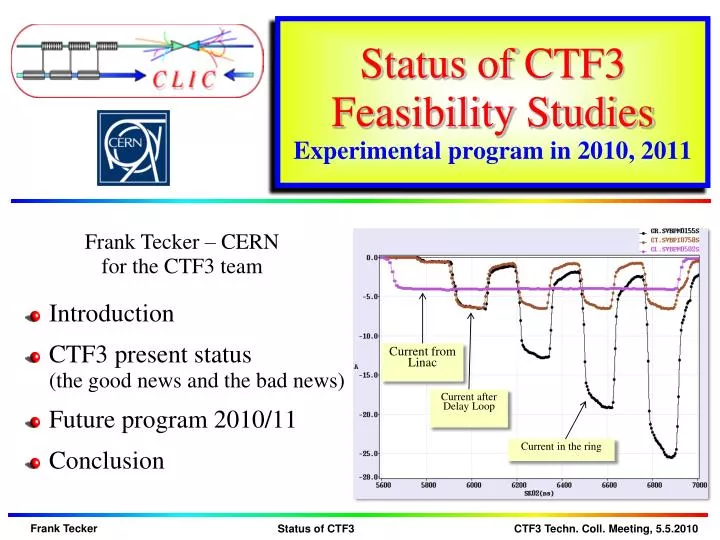
Status of CTF3 Feasibility Studies Experimental program in 2010, 2011. Current from Linac. Introduction CTF3 present status (the good news and the bad news) Future program 2010/11 Conclusion. Current after Delay Loop. Current in the ring. CLIC feasibility issues @ CTF3.

E N D
Status of CTF3 Feasibility StudiesExperimental program in 2010, 2011 Current from Linac • Introduction • CTF3 present status(the good news and the bad news) • Future program 2010/11 • Conclusion Current after Delay Loop Current in the ring
recombinationx 4 recombination x 2 bunch lengthcontrol bunchcompression fully loadedacceleration structures12 GHz phase-coding PETSon-off Decelerationstability two-beamacceleration structures 30 GHz CTF3 base line programme CTF3 – R&D Issues - where R1.1 – structuresR1.2 – DB generation R1.3 – PETS on-offR 2.1 – structure materialsR 2.2 – DB deceleratorR 2.3 – CLIC sub-unit R.Corsini
DL 7A Delay loop status • factor 2 combination re-established after 2 years • current about doubled, up to ~7 A (~0.5 A in satellites)current stability 0.22% => details in CR SimonaBettoni Wed 15:00 Current in the Delay Loop Current after Delay Loop Current from Linac
15 A Combiner ring status routinely factor 4 combination achieved with 15 A, 280 ns (withoutDL) current stability 0.25% CR 280 ns 280 ns Current from Linac 1st turn of 1st pulse 2nd turn of 1st pulse and 1st turn of 2nd pulse 3rd turn of 1st pulse,2nd turn of 2nd pulse, 1st turn of 3rd pulse Current in the ring All 4 pulses
DL 30A Factor 8 combination (DL+CR) • ~28 A combined achieved, nominal 140 ns pulsecurrent stability 1% CR Current from Linac Current after Delay Loop Current in the ring
Recombination studies • emittance measurement (vertical plane)combined 4x beam < 150 π mm mrad • streak camera measurements Turn 1 Turn 2 • orbit closure well controlled • combination to be optimized • dispersion/isochronicity • more from 666 ps initial bunch spacing Turn 3 from DL Turn 4 83 ps final bunch spacing SimonaBettoni Wed 15:00Anne Dabrowski Thu 9:00
DB scheme - status • quite close to all requirements already at the end of 2009
TBTS – Two beam test stand • Combined beam of Combiner Ring extracted(up to 15A/28A), transported to CLEXused for power production in TBTS and TBL • TBTS: Line for Two-beam acceleration studies • both Drive Beam and Probe Beam to the end • Optics and first breakdown kick measurements • 170 MW (peak) RF power reached inPETS power production structuretotal pulse length ~200 ns • => reached nominal CLIC power (135 MW) • acceleration structure TD24 is installed now talk by Roger Ruber this morningAllessandroCapelletti Wed 16:00GermanaRiddone Thu 16:00
TBL - Test Beam Line / Califes • TBL: Line for deceleration studies • Installation of beam line with all magnetsand BPMsfinished, 1st PETS prototypeinstalled (2-3 more this year) • Beam transported to the end • 10A beam generated 20 MW RFpower in the PETS structure, follows expectation Erik Adli Wed 16:30Fernando Toral Thu 12:00Steffen Doebert Thu 14:00 Califes: Probe beam photo-injector Laser performs well, nominal bunch charge reached, accelerated to 140 MeV Beam transported to the end with ~100% transmission, reliable beam to TBTS Detailed optics studies WilfridFarabolini Thu 9:30
PHIN / Laser status • PHIN: Drive beam photoinjector test • shown up to 2.5 nC, above nominal!also 2.3 nC for long train reached • Beam energy ~ 5-6 MeV • Emittance measured ~7 π mm mrad • Very good agreement with simulations Öznur Mete Thu 11:00Steffen Doebert Thu 11:20 • Laser: (for Califes and PHIN) • all PHIN main parameters fulfilled !!! • 0.8% beam current stability(without feedback on the laser) • long term studies (cathode response, …) to be done • Laser phase coding to be demonstratedthis year Marta Csatari Thu 10:00
Fire in MKS13 Faraday Cage • Thu 4 Mar, lunch time … Faraday Cage Pulse Forming Network after fire Modulator in Gallery Pulse Forming Network in Faraday Cage
Events and actions • Modulator turned on around 12h00 • Smoke alarm level 3 at fire service 12h33 • Fire Service in place at 12h42Smoke from MKS 13General emergency stop activated • All electricity (including MKS13) cutapart from lift and smoke extraction system • CO2 , powder, then water and eventually foam applied => corrosive!!! • Fire extinguished around 16h00 • Building access refused to everyone apart from fire service and safety commission • Cleaning company BELFOR contacted for swab testing to check contamination of zone • Safety commission enquiry started Surveillance camera image
Clean up • Gallery partitioned initially into 2 zones (clean up area + “clean area”) • Clean up of contaminated area estimated > 4 weeks • New swab test on equipment in “clean area” • contamination of ventilation ducts • Clean up scheduled for 6 weeks • cleaning finished 27 April (most of it even before) • All electrical systems locked off • gallery classified as non controlled area (cleaning firm didn’t need film badges) => no beam or RF possible Contaminated area from MKS12
Cleaning procedure Components from each rack dismounted and identified Dust removal from sub components Chemical cleaning Cleaned components waiting for reinstallation in gallery Ovens for drying after chemical cleaning Vacuum ovens for 2nd stage
Damaged cables • >300 cables and ~40 HV vacuum cables in front of PFN damaged • All cables will be repaired – 4 ½ weeks estimated => until 26 May • complete replacement (vacuum) • replace damaged section with connectors at both ends • consequence: • all power still disconnected in the klystron gallery => until 20 May • vacuum pumps off in Delay Loop, Combiner Ring + part of linac • problem: testing of connections => bumpy start-up?
Restart planning • Meeting on Wednesday 24th March with groups and departments who have equipment in the area to define an action plan for recovery after the clean up • meeting yesterday about detailed planning • Fire detection system gets repaired this week=> fire detection tests after re-establishing general power • visual inspection by equipment experts • gradually power on the equipments when powering possible=> hardware + controls tests • modify klystrons for increased safety • restart klystron interlock system for access => safety chain tests • 3-4 weeks after end of cable repair • => restart RF mid june
Fire Consequences • 17 weeks delay with respect to nominal program(42 weeks not including stops)=> >40% of the time lost! • klystron MKS13 not available, acc. structures are removed=> lower energy than before => complete new machine setup • repair of MKS13 man-power limited • difficult start-up with additional HW checks • => only less than half of useful beam time this year=> compromises on the program 2010 have to be made • plan to have minimum winter shutdown and continue operation early in 2011=> the items planned forup to end 2010 extend to mid 2011
DB generation – mid 2011 • Bunch train recombination • Consolidate results, routine operation, stability of fully combined beam • Transverse rms emittance • Complete TL2, TL2’, TBTS commissioning – full transport to CLEX • < 100 π mm mrad after ring, combined beam • < 150 π mm mrad in CLEX, combined beam • Bunch length control to < 1 mm rms (combined beam) • Measurement campaign with different meas. systems(RF defl.& screen, fast streak-camera, RF monitors) • R56 tuning experiments in Frascati chicane and TL2 • Beam current stability: improve slow variations, obtain ~0.2 % for combined beam • Full measurement campaign(find correlations, jitter sources) • Gun pulse flatness, “slow” feedback • Improve overall klystron stability (at least up to best performing klystrons) • Slow RF feedback (temp. in pulse compressors) Alexandra Andersson Wed 17:25AlexeyDubrovskiyWed 17:45
RF structures – mid 2011 • PETS TBTS • Initial configuration with variable power splitter & phase shifter • Fast fall-back solution: recirculation with no active elements(maximum power to accelerating structure) • Goal: nominal power / pulse length inside PETS with recirculation(135 MW, 250 ns total pulse length, 170 ns flat-top) • Breakdown rate measurements(at high BD rate - extrapolation to lower rates) • Operation w/out recirculation – may have different breakdown rate… • Test of new PETS on-off scheme (components and concept) • Acc. structure in TBTS • TD24, initial conditioning in the shadow of PETS operation • Goal: nominal power / pulse length delivered to structure(65 MW, 250 ns total pulse length, 170 ns flat-top)
Two beam issues – mid 2011 • TBTS • Two-Beam test –100 MV/m, consistency between power & beam energy gain • Drive beam, deceleration, power produced • Probe beam, power delivered to accelerating structure, energy gain • Beam Loading compensation experiment - by varying fast phase switches – check control of RF pulse shape with probe beam acceleration • Measurement of breakdown kicks • Measurement of effect of beam loading on breakdown rate • TBL • Measurement of deceleration / produced power • Goal: deceleration by 30% (need 8 PETS installed)Measurement of energy spectrum • Optics, steering algorithm studies
CTF3 beam-loading experiment • model for beam-loading compensation by OleksiyKononenko • phase coding / Full PETS Bunch Response Calculations • applied to CLIC reduced voltage spread from 6% to 0.25% • CTF3 case under study Voltage Spread ≈ 0.25 % CLICoptimized
Other issues – mid 2011 • CALIFES • Fully reach nominal parameters (total charge) • Bunch length measurements (RF defl. & screen) • PHIN • 2010: complete measurement program • 2011: test of phase coding with beam • Other • First measurements of phase stability (PETS output, RF pickups…) • Operation at 5 Hz (or more) • Control of beam losses • Coherent Diffraction Radiation (RHUL collaboration) • … Andrea Ghigo Thu 11:40GiulioMorpurgo Thu 14:30 PavelKarataev Wed 17:00
Schedule 2010 (updated) Optics improvements (DL dispersion) Full transport to CLEX Bunch length control (first tests) TBTS initial PETS tests CALIFES setup new setup when MKS13 available? 1 PETS conditioned to nominal power/pulse lengthTBL PETS tests 2 • Two-Beam test • power & energy gain, 100MV/m Accelerating structure conditioned to nominal power/pulse length 3 PETS breakdown rate measurements??? • TBL studies(limited) 4 1 3 2 • Beam Loading compensation experiment • Measurement of breakdown kicks 5 3 2 1 • Measurement of effect of beam loading on breakdown rate 6 4 5 6 Test of new PETS on-off scheme 7 • TBL studies 30% deceleration ? 8 • Stability studies & improvements • PETS no recirculation • Phase stability • Operation at 5 Hz (or more) • Control of beam losses • Coherent Diffraction Radiation … 6 • 1st TBL PETS installationPHIN possible • <--------> 4 5 • 2nd TBL PETS installation • 6 weeks PHIN • phase-coding • Laser preparation 7 8 7 8
Conclusion • Drive Beam generation very well covered • full bunch train combination2x4shown (DL+CR) • started to address performance and stability • Fire has caused considerable delay • recovery ongoing • next major steps: • two beam acceleration tests in TBTS • drive beam deceleration in TBL • increase beam stability => easier routine operation • CTF3 evolution beyond 2012 • Many THANKS to all collaborators! Roberto Corsini Thu 16:00
Roberto’s commentsbefore the fire CTF3 2010 outlook • Drive Beam Generation • Bunch train recombination 2 x 4 in DL and CR (from 3.5 to 28 A) • Transverse rms emittance < 150πmm mrad (combined beam) • Bunch length control to < 1 mm rms (combined beam) • Beam current stability ~ 0.1 % for combined beam • Drive Beam Power Production & Two Beam Acceleration • 20.8 A beam-powered test of a single PETS (without recirculation) in the TBTS • 135 MW (with 28 A potentially available in CLEX, the peak power can reach 240 MW) • 140 ns total pulse length • A measured breakdown rate in the range of 10-4 or lower • Operation of a few hundred hours at 1 Hz • 7.4(10) A beam-powered test of a single PETS with ext. recirculation in TBTS • 135 (81) MW circulating power or 65 (65) MW available for accelerating testing • 250 ns total pulse length, 100 (170) ns flattish-top • A measured breakdown rate in the range of 10-4 or lower • Operation of a few hundred hours at 5 Hz • On/off/adjust will be demonstrated using the external reflection/recirculation system mounted on one of the PETS in TBL. • TBTS • Improved measurements of power and energy loss. • Breakdown transverse kick measurements. • Probe Beam energy gain and beam loading tests. • TBL • The current schedule is to have 8 PETS installed as well as a spectrometer dump for energy spectrum studies, toward the summer 2010. This will allow to verify transport of a beam with up to 30% of the energy extracted. Will be OK, possibly somewhat reduced performance… Overall reasonable goals, but difficult to have a few hundred hours, and 5 Hz TBTS studies and especially TBL results can happen only quite late in 2010…
State of the art today • ongoing Drive Beam generation demonstration in CTF3. • Full beam loading (95% transfer), high current (up to 5A) in DBA • Sub-Harmonic bunching, phase coding (7% satellites) • Bunch train recombination factor 2 in Delay Loop (up to ~7 A) • Bunch train recombination factor 4 in Combiner Ring (3.8 to 15 A) • Recombination 2x4 DL/CR achieved ~ 28 A • Isochronous operation of ring, ap < 10-4 • Transverse rmsemittance 100 π mm mrad (end of linac only)150 π mm mrad (vert., 4x combination) • Bunch length control to < 1 mm rms (end of linac only) • Control of ring length to better than 0.5 mm • Beam current stability ~ 0.15% end-of-linac, ~0.25% combiner ring
To be addressed … • Dispersion / isochronicity in DL/CR • Full bunch length manipulations in TL2 after combination(we see from RF that the form factor is close to 1) • full beam (28 A) to users (new TL2/CLEX BPM readout) • RF power production in CLEX • Two-beam operation in TBTS (relevant CLIC sub-unit)(we started with CCC operator supervision) • Deceleration stability • Loss management, machine protection system • Satellite bunches • Photo injector option • …
2009 CTF3 experimental program Goals • 30 GHz:One structure test (TM02) +breakdown studies • PHINBeam characterization, reach ½ of nominal bunch charge • CALIFESBeam characterization, beam to TBTS (most likely still reduced current) • Delay LoopBack in operation, retrieve combination x 2 (~ 7 A) • Combiner RingFinal optics checks, isochronicity, put together with DL (> 24 A) • TL2Complete commissioning (tail clipper), bunch length control, > 20 Ato users • TBTSPETS to nominal power/pulse length (15 A, recirculation) • Beam commissioning of probe beam line • First accelerating structure tests (one structure ? – CLIC G) • Two-beam studies (deceleration/acceleration), initial breakdown kicks studies • TBLPETS validation (100 MW, need > 20 A), beam line studies (2-3 PETS ?) • OthersCDR studies in CRM, beam dynamics benchmarking, stability studies, control of beam losses…
RF pulse at structure input MKS05 MKS03 MKS06 MKS07 1.5 µs beam pulse RF pulse at structure output Spectrometer 4 Spectrometer 10 analog signal Full beam-loading acceleration in CTF3 • high current routine operation demonstrated Measured RF-to-beam efficiency 95.3% Theory 96%(~ 4 % ohmic losses)
PHIN Photo-injector • Smaller transverse emittance, shorter bunches, no energy tails, no satellites • Bunch charge lower than present injectorshown up to 2.5 nC, above nominal!, also 2.3 nC for long train reached • Beam energy ~ 5-6 MeV • Emittance measured ~7 π mm mrad • Very good agreement with simulations • started to measure laser/beam stability:better than requirements E-beamsize: x=1.53mm Lasersize: x=0.74mm δ=0.35mm δ=0.15mm
Laser system status • setup significantly improved (beam path, optical crystal,…) • For PHIN all laser main target parameters fulfilled !!! • 0.8% beam current stability (without feedback on the laser) • long term studies (cathode response, …) to be done • Laser phase coding to be demonstrated this year • Booster amplifier needed (~ June)