Download
1 / 34
350 likes | 618 Views
Progress on Z-Pinch IFE and HIF Target Work on Z . Part 1: Z-Pinch IFE concept Part 2: Z-Pinch IFE program plan for FY04 $4M Part 3: HIF/Z-Pinch collaborations: P4 experiments on Z. Craig Olson Sandia National Laboratories Albuquerque, NM 87185.

E N D
Progress on Z-Pinch IFE and HIF Target Work on Z Part 1: Z-Pinch IFE concept Part 2: Z-Pinch IFE program plan for FY04 $4M Part 3: HIF/Z-Pinch collaborations: P4 experiments on Z Craig Olson Sandia National Laboratories Albuquerque, NM 87185 15th Int. Symp. on Heavy Ion Inertial Fusion Princeton University Princeton, NJ June 7-11, 2004 Sandia is a multiprogram laboratory operated by Sandia Corporation, a Lockheed Martin Company, for the United States Department of Energy’s National Nuclear Security Administration under contract DE-AC04-94AL85000.
What has already been accomplished that is relevant to Z-Pinch IFE x-rays:1.8 MJ of x-rays on Z (demonstrated) available now low cost: $30/J for ZR (demonstrated cost) $17/J goal for X-1 high yield study (1999) high efficiency: wall plug to x-rays: ~15% on Z (demonstrated) can be optimized to: ~25% or more capsule compression experiments on Z: double-pinch hohlraum1: Cr 14-20 (demonstrated), symmetry ~3% (demonstrated) dynamic hohlraum2: 24 kJ x-rays absorbed, Cr 10, up to 8x10¹⁰ DD neutrons (demonstrated) hemisphere compression for fast ignition3: Cr 3 (demonstrated) (1Cuneo, et al.; 2Bailey, Chandler, Vesey, et al.; 3Slutz, et al.) repetitive pulsed power: RHEPP magnetic switching technology: 2.5 kJ @ 120 Hz (300 kW ave. pwr. demonstrated) LTD (linear transformer driver) technology: being developed (compact, direct, simple)
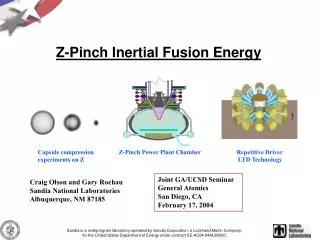
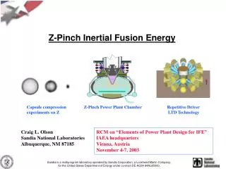
The long-term goal of Z-Pinch IFE is to produce an economically attractive power plant using high-yield z-pinch-driven targets (3 GJ) at low rep-rate per chamber (0.1 Hz) Z-Pinch IFE DEMO (ZP-3, the first study) used 12 chambers, each with 3 GJ at 0.1 Hz, to produce 1000 MWe The near-term goal of Z-Pinch IFE is to address the science issues of repetitive pulsed power drivers, recyclable transmission lines, high- yield targets, and thick-liquid wall chamber power plants
Z-Pinch IFE Team (1000 and 6000, plus Universities &Industry) C. L. Olson,a G. E. Rochau,a S. A. Slutz,a C. W. Morrow,a G. A. Rochau,a R. E. Olson,a A. R. Parker,a M. E. Cuneo,a D. L. Hanson,a G. R. Bennett,a T. W. L. Sanford,a G. A. Chandler,a J. E. Bailey,a W. A. Stygar,a J. L. Porter,a R. A. Vesey,a T. A. Mehlhorn,a K. W. Struve,a M. G. Mazarakis,a L. X. Schneider,a K. R. Prestwich,a G. Benevides,a T. J. Renk,a T. J. Tanaka,a M. A. Ulrickson,a D. H. McDaniel,a M. K. Matzen,a J. P. Quintenz,a W. B. Gauster,a P. F. Peterson,b J. S. De Groot,c R. R. Peterson,d,e D. Kammer,e I. Golovkin,e G. L. Kulcinski,e E. Mogahed,e I. Sviatoslavsky,e M. Sawan,e C. Gibson,fH. Tran,g P. Panchukh, R. Lumiai aSandia National Laboratories, Albuquerque, NM bUniversity of California, Berkeley, CA cUniversity of California, Davis, CA dLos Alamos National Laboratory, Los Alamos, NM eUniversity of Wisconsin, Madison, WI fGeneral Atomics, San Diego, CA gUniversity of New Mexico, Albuquerque, NM hEG&G, Albuquerque, NM iInControl, Inc., Albuquerque, NM US/Russia collaboration on Z-Pinch IFE -
2038 2024 2018 2012 2008 2004 1999 Z-Pinch IFE Road Map Z-Pinch IFE DEMO Z-Pinch ETF $1B Laser indirect-drive Ignition Z-Pinch High Yield Z-Pinch Ignition HY Z-Pinch IRE $150M (TPC) +op/year Z-Pinch IFE target design $5M /year Z-Pinch IFE target fab., power plant technologies $5M /year FI ZR Z Z-Pinch IFE PoP $10M /year Z-Pinch IFE target design $2M /year Z-Pinch IFE target fab., power plant technologies $2M /year Z-Pinch IFE CE $400k /year (SNL LDRD +) NIF Year Single-shot, NNSA/DP Repetitive for IFE, OFES/VOIFE
Driver pulsed power: _________ Marx generator/ magnetic switching linear transformer driver water line technology (RHEPP technology) (LTD technology) Power feed: ____ triax coax RTL: ____ Flibe/electrical coating Flibe immiscible material (e. g., low activation ferritic steel) Target: __ double-pinch dynamic hohlraumfast ignition Chamber: _ dry-wall wetted-wall thick-liquid wall solid/voids Z-Pinch IFE Matrix of Possibilities (choose one from each category) Z-Pinch Driver: ______________ Marx generator/ magnetic switching linear transformer driver water line technology (RHEPP technology) (LTD technology) RTL (Recyclable Transmission Line): _____ Flibe/electrical coating immiscible material (e. g., low activation ferritic steel) Target: _ double-pinch dynamic hohlraumfast ignition Chamber: ____ dry-wall wetted-wall thick-liquid wall solid/voids (e. g., Flibe foam) Mainly science: z-pinch target physics Mainly engineering/technology: z-pinch driver, RTL, chamber
Z-pinches offer the promise of a cost-effective energy-rich source of x-rays for IFE X-1 (total energy) ZX ZR Z Saturn Proto II Supermite ZR will be within a factor of 2-3 in current (4-9 in energy) of a High Yield driver.
(all are 60 MA) ( 90 MA) ( 60 MA) (28 MA) (18 MA) (10 MA) (10 MA) (1 MA)
Linear Transformer Driver (LTD) technology is compact and easily rep-rateable • LTD uses parallel-charged capacitors in a cylindrical geometry, with close multiple triggered switches, to directly drive inductive gaps for an inductive voltage adder driver (Hermes III is a 20 MV inductive voltage adder accelerator at SNL) • LTD requires no oil tanks or water tanks • LTD study (as shown) would produce 10 MA in about 1/4 the size of Saturn • LTD pioneered in Tomsk, Russia Modular High Efficiency (~ 90% for driver) Low Cost Switches: ball-gaps in air, pressurized gas, solid-state Easily rep-rateable for 0.1 Hz
Z-pinch power plant chamber uses an RTL (Recyclable Transmission Line) to provide the standoff between the driver and the target INSULATOR STACK (connects to driver) RTL FLIBE JETS Z-PINCH TARGET 10-20 Torr Inert Gas Yield and Rep-Rate: few GJ every 3-10 seconds per chamber (0.1 Hz - 0.3 Hz) Thick liquid wall chamber: only one opening (at top) for driver; nominal pressure (10-20 Torr) RTL entrance hole is only 1% of the chamber surface area (for R = 5 m, r = 1 m) Flibe absorbs neutron energy, breeds tritium, shields structural wall from neutrons Eliminates problems of final optic, pointing and tracking N beams, high speed target injection Requires development of RTL
Recyclable Transmission Line (RTL) status/issues RTL movement (“automobile assembly line technology”)* RTL electrical turn-on* RTL low-mass limit and electrical conductivity* RTL structural properties/ chamber pressure* RTL mass handling* RTL shrapnel formation RTL vacuum connections/ electrical connections* RTL activation/ waste stream analysis* RTL shock disruption to fluid walls RTL manufacturing/ cost* RTL optimum configuration (coax, triax, convolute, shape, inductance, material, mass) RTL power flow limits (physics of magnetic insulation) Effects of post-shot EMP, plasma, droplets, debris up the RTL Shielding of sensitive accelerator/power flow feed parts ... * initial investigations during LDRD phase considerable list of science issues remains
RTL research completed under LDRDs RTL electrical turn-onSaturn experiments (2000) tin, Al, stainless-steel all show negligible losses RTL low-mass andSaturn experiments (2001) electrical conductivity 20 mylar; 50, 100, 250 steel RTL mass could be as low as 2 kg RTL mass 50 kg has low resistive losses RTL structural Calculations (U. Wisconsin) (2002) full-scale RTL (50 kg) of 25 mill steel ok for background pressure 10-20 Torr RTL manufacturing (allowed RTL budget is a few $ for 3 GJ) Flibe casting ($0.70/RTL) ferritic steel stamping ( $1.20-3.95/RTL)
RTL Structural RTL FINITE ELEMENT MODEL constructed in ANSYS to perform structural analysis R = 50 cm r = 5 cm L = 200 cm 25 mil steel disc 10 cm lip Fusion Technology Institute University of Wisconsin, Madison
RTL Structural PRELIMINARY BUCKLING ANALYSIS of steel RTL 78 Torr RTL buckles at 1.52 psi = 78 Torr as shown 20 Torr no effect (safe operating point) Fusion Technology Institute University of Wisconsin, Madison
Laser Source Cones 5.5 mm 10 mm NIF Scale Z-pinch-driven-hohlraums have similar topology to laser-driven-hohlraums, but larger scale-size Double ended hohlraum 35 mm Dynamic hohlraum 6 mm
Code calculations and analytic scaling predict z-pinch driver requirements for IFE DEMO Double-Pinch Hohlraum Dynamic Hohlraum current /x-rays Eabs / yield current /x-rays Eabs / yield 54 – 95 MA 12-37 MJ 2.4 – 7.2 MJ 530 – 4400 MJ 2 x 62-68 MA 2 x (16-19) MJ 1.3 – 2.6 MJ 400 – 4000 MJ Based on these results, an IFE target for DEMO will require: double-pinch hohlraumdynamic hohlraum 36 MJ of x-rays (2x66MA) 30 MJ of x-rays (86 MA) 3000 MJ yield 3000 MJ yield (G = 83) (G = 100) J. Hammer, M. Tabak, R. Vesey, S. Slutz, J. De Groot
Thick liquid walls essentially alleviate the “first wall” problem, and can lead to a faster development path
Z-Pinch IFE Program Plan for $4M for FY04
Key Scientific Question for Z-Pinch IFE Given that the key target physics issues are being addressed in the NNSA DP ICF program, the key scientific question for z-pinch IFE is: “Can a repetitive pulsed power driver be connected directly to a fusion target with a recyclable transmission line to make an attractive inertial fusion energy power plant?”
Primary Issues for Z-Pinch IFE For this Initiative, research is proposed to address the following primary issues for z-pinch IFE: 1. How feasible is the RTL concept? 2. What repetitive pulsed power drive technology could be used for z-pinch IFE? 3. Can the shock from the high-yield target (~3 GJ) be effectively mitigated to protect the chamber structural wall? 4. Can the full RTL cycle (fire RTL/z-pinch, remove RTL remnant, insert new RTL/z-pinch) be demonstrated on a small (PoP) scale? 5. What is the optimum high-yield target for 3 GJ, and what are the power flow requirements for this target? 6. What is the optimum power plant scenario for z-pinch IFE? 7. What is the path forward for z-pinch IFE?
Task 1. Recyclable Transmission Line (RTL) • Deliverables: • Develop integrated solutions to the RTL issues (RTL shape, materials, inductance, physics of power flow, chamber/interface issues, etc.) to validate the credibility and practicality of the RTL concept. • Design, build, and begin structural testing of RTLs to be used in 1 MA PoP experiments in subsequent FYs. • Design, cost, and schedule an RTL demonstration on Z/ZR. • Initiate a baseline RTL conceptual design for a 60 MA driver for a High Yield/ Engineering Test Facility (ETF).
Task 2. Repetitive Driver Development • Deliverables: • Assess the three approaches to repetitive pulsed power • for z-pinch IFE to validate LTD technology is the best • approach. • Form a standing working group to assess and develop • long-lifetime repetitive switches (ball-gaps in air, pressurized gas, magnetic switching, solid-state, etc.) for z-pinch IFE. • Develop an explicit conceptual power flow plan for a z-pinch IFE driver, using LTD technology coupled to an RTL to a z-pinch target. Include details of the RTL/MITL interface. • Initiate development of a 1 MA, 1 MV, 100 ns, 0.1 Hz driver using LTD technology as a PoP scale driver. Utilize and complement existing SNL work at Tomsk (Russia) on LTD technology. • Collaborate with the HIF-VNL on the possible use of LTD technology for HIF drivers.
Summary of Collaborating Institutions Collaborating National Laboratories: LLNL, LBNL, LANL, NRL, INEEL* Collaborating Universities: UCB, U.Wisc., UCD, UCLA, Georgia-Tech, U. Missouri*, Texas Tech*, UNM, UNR*, Cornell*, UCSD Collaborating Industry: PSI, GA, Luxel, MRC, FPA Collaborating Institutions in Russia: Kurchatov (Moscow), Institute for High Current Electronics (Tomsk) Institute for Theoretical and Experimental Physics (Moscow) *Potential Collaborator
HIF and Z-Pinch Collaboration Areas indirect-drive targets1 - e.g. P4 symmetry thick liquid walls2 LTD driver technology target fabrication waste stream analysis 1see D. Callahan, talk M.I-06 2see W. Meier, talk F.I-05
Symmetry Control Developments:Radiation Shimming in Double-Ended Hohlraums Roger Vesey, Guy Bennett, Debra Callahan*, Mike Cuneo, Max Tabak*, John Porter, R. Adams, P. Rambo, L. Ruggles, W. Simpson, and I. Smith * LLNL HIF hybrid target Double z-pinch target on Z
We diagnose radiation asymmetry on Z with x-ray point-projection backlighting of an imploding capsule Z-Beamlet Laser beam Secondary hohlraum X-ray film Target foil (e.g. Fe) 2 x 16 MA 40 TW/side 1 MJ negative P4 flux positive P4 flux RAV6-2004 2
HIF target calculations with and without the shim layer show the improvement in symmetry* Applied radiation source with -12% P4 in flux during foot pulse Contours of imploded shell density near ignition time Au shim (thickness exaggerated) @ 19.3 g/cc 2.3 mm CH 1.044 g/cc 2.01 mm DT 0.25 g/cc 1.66 mm DT gas 0.6 mg/cc < 1 MJ 393 MJ Fusion yield • Radiation shim layer placed directly on the capsule surface may work for high-convergence, high yield capsules (simple target fab) • 0.9 to 1.3x nominal shim thickness also produced nearly 1D yield RAV 6-2004 9 *D. Callahan APS-DPP 2003
The first rad-shimmed capsule shots on Z in April, 2004 were successful in demonstrating the potential Chose Z hohlraum which previously gave good data on –P2 and –P4 Capsule is 4.7-mm diameter, 30-mm thick CH shell with 2% Ge dopant for increased backlighter contrast at 6.7 keV Gold shim layer designed (Callahan) to zero out both P2 and P4 Shim layer as deposited was somewhat thicker at equator and somewhat thinner near P4 extrema than designed Unshimmed capsule: Shim blowoff 1048 1276 Capsule P2 = - 6.0 % P4 = - 6.9 % P2 = + 15 % P4 = - 3.0 % design sim. RAV 6-2004 10
Refinements for September, 2004 series on Z include: Improved shim quality for P4 Gold shim thickness vs. polar angle Shim characterized by Abbas Nikroo (General Atomics) 1.0 0.9 0.8 • Coating masks on flat vs. spherical surface resulted in different profiles • Target required coating masks for both P2 and P4 to be developed 0.7 Thickness (mm) 0.6 0.5 0.4 0.3 0 50 100 150 • Sept series uses hohlraum designed for zero P2, resulting in thinner overall shim to remove the remaining P4 asymmetry • GA will redesign the coating mask to remove the thickness discrepancies • Target development is only pushed by actually having shots on the schedule RAV 6-2004 12
Radiation shims appear promising for removing early time asymmetries in ICF and IFE capsules • Calculations show that shims can take out significant early time asymmetries • This may open up new possibilities such as smaller case-to-capsule ratio and different hohlraum geometries • Rad-shimmed capsules can now be coated, characterized, and mounted accurately to perform symmetry control experiments on Z • Demonstration of rad-shim performance will occur on Z and will impact target designs for: • Heavy-ion fusion • Z-pinch double-ended hohlraums • Z-pinch dynamic hohlraums • NIF hohlraums RAV 6-2004 13