Download
1 / 10
120 likes | 255 Views
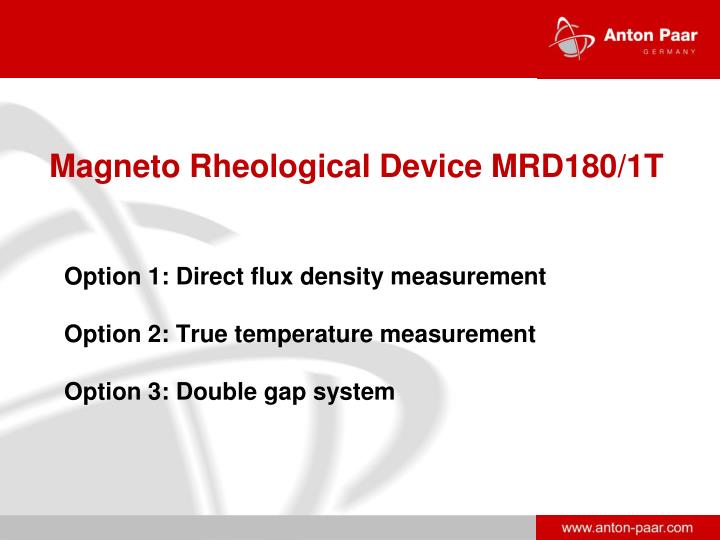
Magneto Rheological Device MRD180/1T Option 1: Direct flux density measurement Option 2: True temperature measurement Option 3: Double gap system. Temperature controlled joke. Hall sensor slot. MRF- Magneto Rheological Fluid. Plate for magnetic fluxdensity measurements. Coils.

E N D
Magneto Rheological Device MRD180/1T Option 1: Direct flux density measurement Option 2: True temperature measurement Option 3: Double gap system
Temperature controlled joke Hall sensor slot MRF- Magneto Rheological Fluid Plate for magnetic fluxdensity measurements Coils Temperature controlled bottom plate MRD180/1T • The new Magneto Rheological Device MRD180/1T consists of: • Temperature controlled joke and bottom plate • Plate PP20 • Slot for Hall sensor (ready for direct measurement of the magentic field) • Power supply controlled by software
Features and Benefit of MRD180/1T • Application of a magnetic field during a rheological test • Magnetic flux density controllable via software • Reading of the set values and analysis of the actual magnetic field in the software after the test (no direct magnetic field measurement) • Software controlled demagnetization • Fluid circulator temperature control to remove the heat produced by the coils and to control the sample temperature • Convenient handling • Ready for magenetic field measurement option • Ready for double gap measurement option
Analog Output to MCR Zero Gauss Chamber Hall Sensor Option 1: Direct Magnetic Field Measurements Tesla Meter • Integration of a Hall sensor in the bottom plate of the MRD for online magnetic flux density measurements • Online reading and display of the real actual values in the software
Features and Benefits Option 1:Direct Magnetic Field Measurement • True Flux density measurement • No calibration or analysis required due to changing permeability. The flux density is measured. • Sample permeability can be calculated for different flux densities • Magnetic field along the plate radius measurable (proof of simulations) • Monitoring of MRF switching times Simulation data provided by Dr. H. M. Laun et al. BASF Ludwigshafen, 2006
Example Option 1: Switching times in MRF Short switching times are required in MRF application • Delay times: • switch on: 2.8 ms • switch off: 1.8 ms Switching on and off of the magnetic field (torque in blue, magnetic flux density in red). Unfiltered raw data sampling of the MCR rheometer (sampling rate 0.1 ms, special firmware) in combination with direct magnetic flux density measurements (option 1) enable the monitoring of switching times. Example data provided by Dr. H. M. Laun et al. BASF Ludwigshafen
Option 2: True temperature measurement The magnetic field is produced by a flowing current in the coils. Therefore the coils heat up so that the temperature needs to be controlled by a fluid circulator. The occuring sample temperature is therefore influenced by the heat transferred from the coils to the circulating liquid and should be measured as close as possible to the sample. The „true temperature option“ enables the accurate measurement of the sample temperature with an external temperature sensor in the MRD.
Temperature controlled joke MRF Coils Temperature controlled bottom plate Option 3: Double Gap Measuring System Hall sensor slot Plate for magnetic flux density measurements • Double gap measuring system (DG 16) for shear rates up to 3000 1/s • DG 16 is made of iron • Homogenous magnetic field up to 1.2 T • Direct flux density measurement possible as well
Features and Benefits Option 3: Double Gap Measuring System • Shear rate range increased from 0.3 to 3000 1/s • No gap draining of the sample • Magnetic flux densities up to 1.2 Tesla due the magnetic rotor • Measurement of true flux densities using the Hall sensor • Double gap system patented by BASF and licensed exclusively to Anton Paar
Example Option 3:Double gap measuring system Shear stress [kPa] End of PP 20 shear rate regime Shear rate [1/s] MRF measured in at magnetic flux densities from 0 to 1 Tesla.