Download
1 / 26
260 likes | 434 Views
Embedded Control Applications II MP10- 1. Embedded Control Applications II MP10- 2. Control of a DC servo-motor.

E N D
Embedded Control Applications II MP10-2 Control of a DC servo-motor - The control of a DC servo motor is another common task in robotics / mechatronics; DC servo-motors combine regular DC-motors with a gear-box and an encoder/potentiometer to form a position control loop • Being position controlled, the drive shaft of a servo-motor can only assume a limited range of angular positions (typically ±90° or less) • The set-point is a Pulse Width Modulated (PWM) signal with a period of commonly around 20 ms and duty cycles of 2% to 10% (~0.5 ms to ~2.5 ms)
Embedded Control Applications II MP10-3 Control of a DC servo-motor Encoder / Potentiometer Power amplifier Gear-box DC motor
Embedded Control Applications II MP10-4 Control of a DC servo-motor - Servo-motors have 3 wires: Vsupp,VGNDand signal - Only the signalline interfaces to the microcontroller – the current carrying supply lines need to be connected to a sufficiently powerful supply; typical supply voltages range between 6 V and 30 V red 6 V DC 10% duty cycle black yellow 20 ms
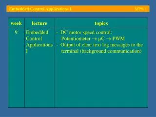
S Embedded Control Applications II MP10-5 Control of a DC servo-motor A small DC servo-motor is to be driven using an edge aligned PWM signal on P7.3 (period: 20 ms). The duty cycle is to be controlled by the analogue voltage applied to ADC channel 4, which is also logged on a terminal connected to ASC port S0 (57600 bps) P5.4 5V PORT 5 PORT 7 PORT 3 10 V 0V RxD P7.3 TxD 0V
Embedded Control Applications II MP10-6 Control of a DC servo-motor - This is essentially the program developed in lecture MP9; the period of the PWM signal has to be adjusted to 20 ms and the duty cycle needs limited to the range from 3 % (0.6 ms) to 10 % (2 ms) - To produce the required 20 ms signal (50 Hz) the PWM module needs to be set up with a pre-scale factor of 1/64; a 12-bit resolution is to be expected (mode: 0), i. e. 2010-3/4096 4.8810-6 s 5µs
Embedded Control Applications II MP10-7 Control of a DC servo-motor - Running the modified program on the C167 confirms a 20 ms period with pulses ranging from 0.6 ms (setting: 0 %) to 2 ms (setting: 100 %)
Embedded Control Applications II MP10-8 Control of a DC servo-motor - The terminal logs the current position as a percentage of the range of admissible pulse widths
Embedded Control Applications II MP10-9 Control of a stepper motor [1] - A stepper motor is an electromechanical device which converts electrical pulsesinto discrete mechanical movements - The shaft or spindle of a stepper motor rotates in discrete step increments when electrical command pulses are applied to it in the proper sequence - This sequence is directly related to the direction of rotation of the motor shaft; the speed of the rotation is directly related to the frequency of the applied pulse sequence
Embedded Control Applications II MP10-10 Control of a stepper motor Stepper motors have the following characteristics: - The rotation angle of the motor is predictably related to the input pulse pattern - The motor has full torque at stand-still (if the windings are energized) - Precise positioning and repeatability of movement; good stepper motors have an accuracy of 3 – 5 % of a step – this error is non-cumulative from step to step - Excellent response to starting, stopping, reversing
Embedded Control Applications II MP10-11 Control of a stepper motor Stepper motors have the following characteristics: - Stepper motors are brushless and thus very reliable; their life span usually only depends on their bearings - They allow for accurate open-loop control; the position can be tracked simply by counting pulses - They allow for very low speed synchronous operation with loads that are directly coupled to the shaft - Improper control may cause resonance phenomena - Difficult to operate at extremely high speeds
Embedded Control Applications II MP10-12 Control of a stepper motor Three different kinds of stepper motors exist: - Variable-reluctance (VR) stepper motors consist of a soft iron multi-toothed rotor and a wound stator - Energizing the stator windings with DC currents causes the poles to be magnetized - Rotation occurs when the rotor teeth are attracted to the energized stator poles
Embedded Control Applications II MP10-13 Control of a stepper motor Three different kinds of stepper motors exist: - Permanent-Magnet (PM) stepper motors (‘tin can’) are low cost and low resolution type motors – typical step angles range from 7.5° to 15° - The rotor no longer has teeth (cf. VR motor), but is magnetized with alternating north and south poles - The increased magnetic flux intensity gives the PM motor an improved torque characteristic
Embedded Control Applications II MP10-14 Control of a stepper motor Three different kinds of stepper motors exist: - Hybrid (HB) stepper motors combine the best features of PM and VR type stepper motors; step angles vary from 3.6° to 0.9° (100 – 400 steps per revolution) - The rotor is teethed with an axially magnetized concentric magnet around the shaft - The teeth on the rotor help guiding the magnetic flux; this leads to increased performance
Embedded Control Applications II MP10-15 Control of a stepper motor - The stator windings need to be energized in such a way as to generate a rotating magnetic field; the rotor follows this field due to magnetic attraction - Two-phase example:Energizing the windings using a B-A-B-A-B-… pattern leads to clockwise rotation - The rotational speed depends on the frequency of the alternating sequence
Embedded Control Applications II MP10-16 Control of a stepper motor - The torque of a stepper motor depends on the step rate as well as the intensity of the magnetic flux in the windings which, in turn, is proportional to the drive current - A stepper motor usually has 2 phases; more complicated designs with 3 and even 5 phases exist - A pole can be defined as one of the regions where the magnetic flux density is concentrated; there are poles on both the rotor as well as on the stator - Increasing the number of poles on rotor and/or stator leads to smaller basic stepping angles (full step)
Embedded Control Applications II MP10-17 Control of a stepper motor - Example: Unipolar 2-phase stepper motor with one pair of poles per phase and one pair of rotor poles - The flux can be reversed by switching the supply from phase A/B to phase A/B
Embedded Control Applications II MP10-18 Control of a stepper motor - Example: Bipolar 2-phase stepper motor with one pair of poles per phase and one pair of rotor poles - The flux can be reversed by swapping the + and - terminals of the supply - 8 full step positions are possible (basic step angle: 45°)
Embedded Control Applications II MP10-19 Control of a stepper motor - The most common stepping modes are wave drive, full step driveand half step drive - In a wave drive system only one phase is energized at any given time; sequence: A B A B … leads to steps from 8 2 4 6 (see MP10-18) - In a full step drive system two phases are energized at any time; sequence: AB AB AB AB … leads to steps from 1 3 5 7 (see MP10-18) - A half step drive system combines the above two modes; sequence: AB B AB A AB B AB A … (1 2 3 4 5 6 7 8)
Embedded Control Applications II MP10-20 Control of a stepper motor - The advantage of full step driveover wave drive is that, at any given time, a full step system uses 50% of the available windings whereas the equivalent wave drive system only uses 25% - Furthermore, unipolar stepper motors only use 50% of each winding to build up the magnetic flux; bi-polar stepper motors on the other hand use the full winding and therefore produce more torque - Microstepping systems continuously vary the current amplitude in the windings to break up a basic step into many smaller discrete steps
Embedded Control Applications II MP10-21 Control of a stepper motor - The stiffness of a stepper motor can be increased by increasing its holding torque (TH); moving the drive shaft away from an equilibrium position (rotor and stator poles are aligned) leads to an opposing torque which increases until TH is reached - Beyond the holding torque, the rotor position becomes unstable and it moves until it is aligned with the next stator pole
Embedded Control Applications II MP10-22 Control of a stepper motor - The torque vs. speed characteristic of a stepper motor indicates its pull-in curve (defines a region at which the motor can be started/stopped without loss of synchronism)… - … as well as its pull-out curve (limits the slew region, i. e. the region within which the motor can be operated without loss of synchronism)
Embedded Control Applications II MP10-23 Control of a stepper motor - The time-domain response of a single step is subject to load conditions and the maximum required acceleration - Driving the motor at frequencies near the natural frequency of the rotor can lead to resonance; this resonance manifests itself in a sudden loss or drop in torque at certain speeds which can lead to loss of synchronism
Embedded Control Applications II MP10-24 Control of a stepper motor - The driver of a stepper motor can be implemented using a microcontroller; the controller needs to produce the required pulse sequence and interface to an array of inverters or power MOSFETs - This would only be done for educational purposes; in the ‘real world’ a stepper motor driver chip would be used (cost: ‘a few dollars’) - This reduces the task to the provision of a pulse sequence, the frequency of which defines the rotational speed, and a directional signal (fw. / rev.)
Embedded Control Applications II MP10-25 Control of a stepper motor - A typical design of a stepper motor driver is shown below; note that the transistors of the power amplifier often have to be implemented externally
Embedded Control Applications II MP10-26 Further reading: [1]Douglas W. Jones, Control of Stepping Motors – A Tutorial,http://www.cs.uiowa.edu/~jones/step/, accessed: January 2005 [2]ELF/DWARF, Free Standards Group – Reference Specifications, www.linuxbase.org/spec/refspecs/, accessed: January 2005 [3]The GCC Project, Free Software Foundation,gcc.gnu.org/, accessed: January 2005