Download
1 / 37
410 likes | 967 Views
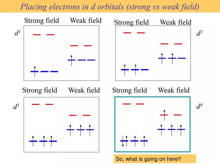
Placing electrons in d orbitals (strong vs weak field). d 1. d 2. d 4. d 3. Strong field Weak field. Strong field Weak field. Strong field Weak field. Strong field Weak field. So, what is going on here!!.

E N D
Placing electrons in d orbitals (strong vs weak field) d1 d2 d4 d3 Strong field Weak field Strong field Weak field Strong field Weak field Strong field Weak field So, what is going on here!!
When the 4th electron is assigned it will either go into the higher energy eg orbital at an energy cost of D0 or be paired at an energy cost of P, the pairing energy. Strong field Weak field d4 Pairing Energy!!. Strong field = Low spin (2 unpaired) Weak field = High spin (4 unpaired) D0, P < Do P > Do
Pairing Energy, P • The pairing energy, P, is made up of two parts. • Pc: Coulombic repulsion energy caused by having two electrons in same orbital. Destabilizing energy contribution of Pc for each doubly occupied orbital. • Pe: Exchange stabilizing energy for each pair of electrons having the same spin and same energy. Stabilizing contribution of Pe for each pair having same spin and same energy • = sum of all Pc and Pe interactions How do we get these interactions?
Placing electrons in d orbitals d5 d6 d7 1 u.e. 5 u.e. 0 u.e. 4 u.e. 1 u.e. 3 u.e. d8 d9 d10 1 u.e. 1 u.e. 2 u.e. 0 u.e. 0 u.e. 2 u.e. High Low High Low High Low
Detail working out…. d5 1 u.e. 5 u.e. Exchange part = for 3Pe + Pe Exchange part = for 3Pe For 1Pe High Field Low Field (Low Spin) (High Spin) What are the energy terms for both high spin and low spin? Low Field Coulombic Part = 0 High Field Coulombic Part = 2Pc P = 4Pe LFSE = 3*(-2/5D0) + 2 (3/5D0) = 0 P = 2Pc + 4Pe High Field – Low Field = -2D0 +2Pe LFSE = 5 * (-2/5D0) = -2D0 When D0 is larger than Pe the high field arrangement (low spin) is favored.
Interpretation of Enthalpy of Hydration of hexahydrate using LFSE d0 d1 d2 d3 d4 d5 d6 d7 d8 d9 d10 LFSE (in D0) .0 .4 .8 1.2 .6 .0 .4 .8 1.2 .6 .0
Splitting of d orbitals in a tetrahedral field t2 Dt e Dt = 4/9Do Always weak field (high spin)
Extreme elongation: from octahedral tosquare planar Less repulsions along the axes where ligands are missing
A correction to preserve center of gravity A crystal-field aproach: from octahedral to square planar
Magnetic properties of metal complexes Diamagnetic complexes very small repulsive interaction with external magnetic field no unpaired electrons Paramagnetic complexes attractive interaction with external magnetic field some unpaired electrons
Coordination Chemistry: Molecular orbitals for metal complexes
The symmetry of metal orbitals in an octahedral environment A1g T1u
The symmetry of metal orbitals in an octahedral environment T2g Eg
s The symmetry of metal orbitals in an octahedral environment
Metal-ligand s interactions in an octahedral environment Six ligand orbitals of s symmetry approaching the metal ion along the x,y,z axes We can build 6 group orbitals of s symmetry as before and work out the reducible representation
s If you are given G, you know by now how to get the irreducible representations G = A1g + T1u + Eg
anti bonding “metal character” non bonding 12 s bonding e “ligand character” “d0-d10 electrons” 6 s ligands x 2e each
Introducing π-bonding 2 orbitals of π-symmetry on each ligand We can build 12 group orbitals of π-symmetry
Gπ = T1g + T2g + T1u + T2u The T2g will interact with the metal d t2g orbitals. The ligand pi orbitals do not interact with the metal eg orbitals. We now look at things more closely.
Anti-bonding LUMO(π) First, the CN- ligand
Some schematic diagrams showing how p bonding occurs with a ligand having a d orbital (such as in P), or a p* orbital, or a vacant p orbital.
anti bonding “metal character” non bonding 12 s bonding e “ligand character” ML6s-only bonding “d0-d10 electrons” The bonding orbitals, essentially the ligand lone pairs, will not be worked with further. 6 s ligands x 2e each
Do Do has increased D’o Stabilization π-bonding may be introduced as a perturbation of the t2g/eg set: Case 1 (CN-, CO, C2H4) empty π-orbitals on the ligands ML π-bonding (π-back bonding) These are the SALC formed from the p orbitals of the ligands that can interac with the d on the metal. t2g (π*) t2g eg eg t2g t2g (π) ML6 s-only ML6 s + π (empty π-orbitals on ligands)
D’o Do has decreased Do Destabilization Stabilization π-bonding may be introduced as a perturbation of the t2g/eg set. Case 2 (Cl-, F-) filled π-orbitals on the ligands LM π-bonding eg eg t2g (π*) t2g t2g t2g (π) ML6 s-only ML6 s + π (filled π-orbitals)
Strong field / low spin Weak field / high spin Putting it all on one diagram.
Spectrochemical Series Purely s ligands: D: en > NH3 (order of proton basicity) • donating which decreases splitting and causes high spin: • D: H2O > F > RCO2 > OH > Cl > Br > I (also proton basicity) p accepting ligands increase splitting and may be low spin D: CO, CN-, > phenanthroline > NO2- > NCS-
Merging to get spectrochemical series CO, CN- > phen > en > NH3 > NCS- > H2O > F- > RCO2- > OH- > Cl- > Br- > I- Weak field, p donors small D high spin Strong field, p acceptors large D low spin s only
Turning to Square Planar Complexes Most convenient to use a local coordinate system on each ligand with y pointing in towards the metal. py to be used for s bonding. z being perpendicular to the molecular plane. pz to be used for p bonding perpendicular to the plane, p^. x lying in the molecular plane. px to be used for p bonding in the molecular plane, p|.
ML4 square planar complexes ligand group orbitals and matching metal orbitals s bonding p bonding (in) p bonding (perp)
Sample π- bonding ML4 square planar complexes MO diagram eg s-only bonding
Angular Overlap Method An attempt to systematize the interactions for all geometries. The various complexes may be fashioned out of the ligands above Linear: 1,6 Trigonal: 2,11,12 T-shape: 1,3,5 Square pyramid: 1,2,3,4,5 Octahedral: 1,2,3,4,5,6 Tetrahedral: 7,8,9,10 Square planar: 2,3,4,5 Trigonal bipyramid: 1,2,6,11,12
Cont’d All s interactions with the ligands are stabilizing to the ligands and destabilizing to the d orbitals. The interaction of a ligand with a d orbital depends on their orientation with respect to each other, estimated by their overlap which can be calculated. The total destabilization of a d orbital comes from all the interactions with the set of ligands. For any particular complex geometry we can obtain the overlaps of a particular d orbital with all the various ligands and thus the destabilization.
Thus, for example a dx2-y2 orbital is destabilized by (3/4 +6/16) es = 18/16 es in a trigonal bipyramid complex due to s interaction. The dxy, equivalent by symmetry, is destabilized by the same amount. The dz2 is destabililzed by 11/4 es.


![H. Liu [1]* , D. Bedau [1] , D. Backes [1] ,](https://cdn1.slideserve.com/2479170/slide1-dt.jpg)