Download
1 / 5
110 likes | 597 Views
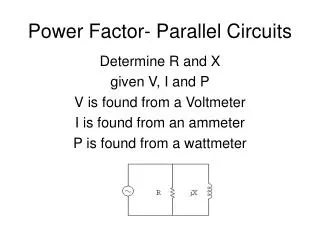
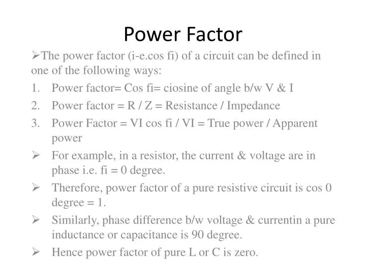
Power Factor. The power factor (i-e.cos fi ) of a circuit can be defined in one of the following ways: Power factor= Cos fi = ciosine of angle b/w V & I Power factor = R / Z = Resistance / Impedance Power Factor = VI cos fi / VI = True power / Apparent power

E N D
Power Factor The power factor (i-e.cos fi) of a circuit can be defined in one of the following ways: Power factor= Cos fi= ciosine of angle b/w V & I Power factor = R / Z = Resistance / Impedance Power Factor = VI cosfi / VI = True power / Apparent power For example, in a resistor, the current & voltage are in phase i.e. fi = 0 degree. Therefore, power factor of a pure resistive circuit is cos 0 degree = 1. Similarly, phase difference b/w voltage & currentin a pure inductance or capacitance is 90 degree. Hence power factor of pure L or C is zero.
This is the reason that power consumed by pure L or C is zero. • For a circuit having R, L & C is varying proportions, the value of power factor will lie b/w 0 & 1. • It may be noted that power factor can never have value greater than 1. • It is a usual practice to attach the word ‘lagging or leading ‘with the the numerical value of power factor to signify wether the current lags or leads the voltage.thus if a circuit has a p.f of 0.5 & the current lags the voltage, we generally write p.f as 0.5 lagging. • Sometimes p.f is experesed as a percentage. Thus 0.8 lagging p.f may be expressed as 80 % lagging.
True power & Reactive power • The purpose of passing current through a circuit is to transfer power from the source to the circuit. • The power which is actually consumed in the circuit is called true power or active power. • As power is consumed only in resistance since neither pure inductor nor the capacitor consumes any active power. • The power consumed ( or true power ) in L & C is zerob/c all the power received from the sourcein one-quarter cycle is returned to the sourcein the next-one quarter cycle. This circulating power is called the reactive powerand does no useful work in the circuit.
As the current & voltage are in phase in a resistance where as they are 90 degree out of phase in L & C. Therefore, we come to the conclusion that I in phase with voltage produces true or active power whereas current 90 degree out of phase with voltage contributes to reactive power, i.e; True power = V * I in phase with voltage Reactive power = V * I 90 degree out of phase with voltage. • Consider an inductive circuit in which I lags behind the applied voltage V by fi degree. • The current I can be resolved into two rectangular components viz, • I cosfi in phase with V and • I sin fi; 90 degree out of phase with V.
True power, P = V * I cosfi watts or KW Reactive power, Q = V*I sin fi VAR or KVAR Apparent power, S = V * I = VI VA or KVA