Download
1 / 40
570 likes | 1.34k Views
RAPID PROTOTYPING. Fundamentals of Rapid Prototyping Rapid Prototyping Technologies Applications and Benefits of Rapid Prototyping. news.thomasnet.com/fullstory/451186. Rapid Prototyping (RP) .

E N D
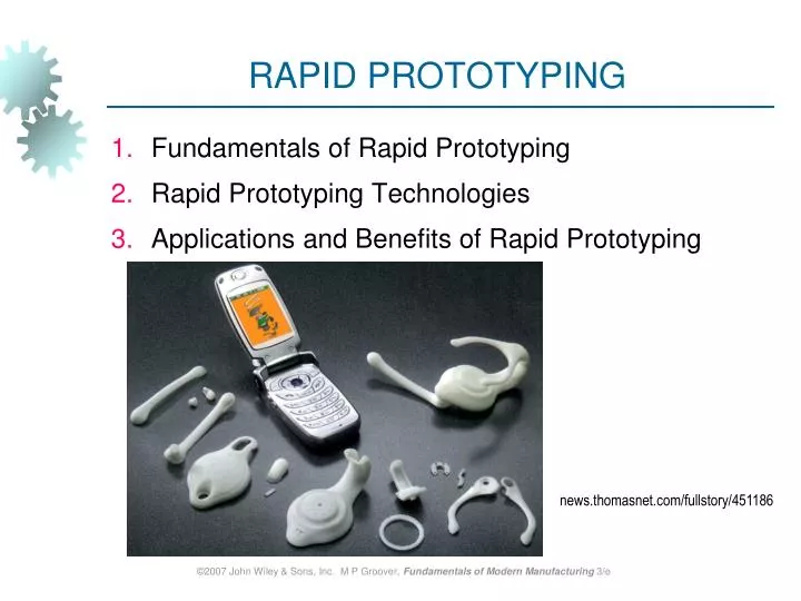
RAPID PROTOTYPING • Fundamentals of Rapid Prototyping • Rapid Prototyping Technologies • Applications and Benefits of Rapid Prototyping news.thomasnet.com/fullstory/451186 ©2007 John Wiley & Sons, Inc. M P Groover, Fundamentals of Modern Manufacturing 3/e
Rapid Prototyping (RP) A family of fabrication processes developed to make engineering prototypes in minimum lead time based on a CAD model of the item • Traditional method is machining • Can require significant lead-times – several weeks, depending on part complexity and difficulty in ordering materials • RP allows a part to be made in hours or days, given that a computer model of the part has been generated on a CAD system ©2007 John Wiley & Sons, Inc. M P Groover, Fundamentals of Modern Manufacturing 3/e
Why is Rapid Prototyping Important? • Product designers want to have a physical model of a new part or product design rather than just a computer model or line drawing • Creating a prototype is an integral step in design • A virtual prototype (a CAD model of the part) may not be sufficient for the designer to visualize the part adequately • Using RP to make the prototype, the designer can see and feel the part and assess its merits and shortcomings ©2007 John Wiley & Sons, Inc. M P Groover, Fundamentals of Modern Manufacturing 3/e
RP – Two Basic Categories: • Material removal RP - machining, using a dedicated CNC machine that is available to the design department on short notice • Starting material is often wax • Easy to machine • Can be melted and resolidified • The CNC machines are often small - called desktop machining • Material addition RP - adds layers of material one at a time to build the solid part from bottom to top ©2007 John Wiley & Sons, Inc. M P Groover, Fundamentals of Modern Manufacturing 3/e
Starting Materials in Material Addition RP • Liquid monomers that are cured layer by layer into solid polymers • Powders that are aggregated and bonded layer by layer • Solid sheets that are laminated to create the solid part Additional Methods • In addition to starting material, the various material addition RP technologies use different methods of building and adding layers to create the solid part • There is a correlation between starting material and part building techniques ©2007 John Wiley & Sons, Inc. M P Groover, Fundamentals of Modern Manufacturing 3/e
Steps to Prepare Control Instructions • Geometric modeling - model the component on a CAD system to define its enclosed volume • Tessellation of the geometric model - the CAD model is converted into a computerized format that approximates its surfaces by facets (triangles or polygons) • Slicing of the model into layers - computerized model is sliced into closely-spaced parallel horizontal layers ©2007 John Wiley & Sons, Inc. M P Groover, Fundamentals of Modern Manufacturing 3/e
Solid Model to Layers Figure 34.1 Conversion of a solid model of an object into layers (only one layer is shown). ©2007 John Wiley & Sons, Inc. M P Groover, Fundamentals of Modern Manufacturing 3/e
More About Rapid Prototyping • Alternative names for RP: • Layer manufacturing • Direct CAD manufacturing • Solid freeform fabrication • Rapid prototyping and manufacturing (RPM) • RP technologies are being used increasingly to make production parts and production tooling, not just prototypes ©2007 John Wiley & Sons, Inc. M P Groover, Fundamentals of Modern Manufacturing 3/e
Classification of RP Technologies • There are various ways to classify the RP techniques that have currently been developed • The RP classification used here is based on the form of the starting material: • Liquid-based • Solid-based • Powder-based ©2007 John Wiley & Sons, Inc. M P Groover, Fundamentals of Modern Manufacturing 3/e
Liquid-Based Rapid Prototyping Systems • Starting material is a liquid • About a dozen RP technologies are in this category • Includes the following processes: • Stereolithography • Solid ground curing • Droplet deposition manufacturing ©2007 John Wiley & Sons, Inc. M P Groover, Fundamentals of Modern Manufacturing 3/e
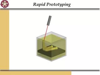
Stereolithography (STL) RP process for fabricating a solid plastic part out of a photosensitive liquid polymer using a directed laser beam to solidify the polymer • Part fabrication is accomplished as a series of layers - each layer is added onto the previous layer to gradually build the 3-D geometry • The first addition RP technology - introduced 1988 by 3D Systems Inc. based on the work of Charles Hull • More installations than any other RP method ©2007 John Wiley & Sons, Inc. M P Groover, Fundamentals of Modern Manufacturing 3/e
Stereolithography Figure 34.2 Stereolithography: (1) at the start of the process, in which the initial layer is added to the platform; and (2) after several layers have been added so that the part geometry gradually takes form. ©2007 John Wiley & Sons, Inc. M P Groover, Fundamentals of Modern Manufacturing 3/e
Figure 34.3 A part produced by stereolithography (photo courtesy of 3D Systems, Inc.). ©2007 John Wiley & Sons, Inc. M P Groover, Fundamentals of Modern Manufacturing 3/e
Facts about STL • Each layer is 0.076 mm to 0.50 mm (0.003 in to 0.020 in.) thick • Thinner layers provide better resolution and more intricate shapes; but processing time is longer • Starting materials are liquid monomers • Polymerization occurs on exposure to UV light produced by laser scanning beam • Scanning speeds ~ 500 to 2500 mm/s ©2007 John Wiley & Sons, Inc. M P Groover, Fundamentals of Modern Manufacturing 3/e
Part Build Time in STL Time to complete a single layer : where Ti = time to complete layer i; Ai = area of layer i; v = average scanning speed of the laser beam at the surface; D = diameter of the “spot size,” assumed circular; and Td = delay time between layers to reposition the worktable ©2007 John Wiley & Sons, Inc. M P Groover, Fundamentals of Modern Manufacturing 3/e
Part Build Time in STL - continued Once the Ti values have been determined for all layers, then the build cycle time is: • where Tc = STL build cycle time; and nl = number of layers used to approximate the part • Time to build a part ranges from one hour for small parts of simple geometry up to several dozen hours for complex parts ©2007 John Wiley & Sons, Inc. M P Groover, Fundamentals of Modern Manufacturing 3/e
Solid Ground Curing (SGC) Like stereolithography, SGC works by curing a photosensitive polymer layer by layer to create a solid model based on CAD geometric data • Instead of using a scanning laser beam to cure a given layer, the entire layer is exposed to a UV source through a mask above the liquid polymer • Hardening takes 2 to 3 s for each layer ©2007 John Wiley & Sons, Inc. M P Groover, Fundamentals of Modern Manufacturing 3/e
Solid Ground Curing Figure 34.4 SGC steps for each layer: (1) mask preparation, (2) applying liquid photopolymer layer,(3) mask positioning and exposure of layer, (4) uncured polymer removed from surface, (5) wax filling, (6) milling for flatness and thickness. ©2007 John Wiley & Sons, Inc. M P Groover, Fundamentals of Modern Manufacturing 3/e
Facts about SGC • Sequence for each layer takes about 90 seconds • Time to produce a part by SGC is claimed to be about eight times faster than other RP systems • The solid cubic form created in SGC consists of solid polymer and wax • The wax provides support for fragile and overhanging features of the part during fabrication, but can be melted away later to leave the free-standing part ©2007 John Wiley & Sons, Inc. M P Groover, Fundamentals of Modern Manufacturing 3/e
Droplet Deposition Manufacturing (DDM) Starting material is melted and small droplets are shot by a nozzle onto previously formed layer • Droplets cold weld to surface to form a new layer • Deposition for each layer controlled by a moving x-y nozzle whose path is based on a cross section of a CAD geometric model that is sliced into layers • Work materials include wax and thermoplastics ©2007 John Wiley & Sons, Inc. M P Groover, Fundamentals of Modern Manufacturing 3/e
Solid-Based Rapid Prototyping Systems • Starting material is a solid • Solid-based RP systems include the following processes: • Laminated object manufacturing • Fused deposition modeling ©2007 John Wiley & Sons, Inc. M P Groover, Fundamentals of Modern Manufacturing 3/e
Laminated Object Manufacturing (LOM) Solid physical model made by stacking layers of sheet stock, each an outline of the cross-sectional shape of a CAD model that is sliced into layers • Starting sheet stock includes paper, plastic, cellulose, metals, or fiber-reinforced materials • The sheet is usually supplied with adhesive backing as rolls that are spooled between two reels • After cutting, excess material in the layer remains in place to support the part during building ©2007 John Wiley & Sons, Inc. M P Groover, Fundamentals of Modern Manufacturing 3/e
Laminated Object Manufacturing Figure 34.5 Laminated object manufacturing. ©2007 John Wiley & Sons, Inc. M P Groover, Fundamentals of Modern Manufacturing 3/e
Fused Deposition Modeling (FDM) RP process in which a long filament of wax or polymer is extruded onto existing part surface from a workhead to complete each new layer • Workhead is controlled in the x-y plane during each layer and then moves up by a distance equal to one layer in the z-direction • Extrudate is solidified and cold welded to the cooler part surface in about 0.1 s • Part is fabricated from the base up, using a layer-by-layer procedure ©2007 John Wiley & Sons, Inc. M P Groover, Fundamentals of Modern Manufacturing 3/e
Powder-Based RP Systems • Starting material is a powder • Powder-based RP systems include the following: • Selective laser sintering • Three dimensional printing ©2007 John Wiley & Sons, Inc. M P Groover, Fundamentals of Modern Manufacturing 3/e
Selective Laser Sintering (SLS) Moving laser beam sinters heat‑fusible powders in areas corresponding to the CAD geometry model one layer at a time to build the solid part • After each layer is completed, a new layer of loose powders is spread across the surface • Layer by layer, the powders are gradually bonded by the laser beam into a solid mass that forms the 3-D part geometry • In areas not sintered, the powders are loose and can be poured out of completed part ©2007 John Wiley & Sons, Inc. M P Groover, Fundamentals of Modern Manufacturing 3/e
Three Dimensional Printing (3DP) Part is built layer-by-layer using an ink-jet printer to eject adhesive bonding material onto successive layers of powders • Binder is deposited in areas corresponding to the cross sections of part, as determined by slicing the CAD geometric model into layers • The binder holds the powders together to form the solid part, while the unbonded powders remain loose to be removed later • To further strengthen the part, a sintering step can be applied to bond the individual powders ©2007 John Wiley & Sons, Inc. M P Groover, Fundamentals of Modern Manufacturing 3/e
Three Dimensional Printing Figure 34.6 Three dimensional printing: (1) powder layer is deposited, (2) ink-jet printing of areas that will become the part, and (3) piston is lowered for next layer (key: v = motion). ©2007 John Wiley & Sons, Inc. M P Groover, Fundamentals of Modern Manufacturing 3/e
RP Applications • Applications of rapid prototyping can be classified into three categories: • Design • Engineering analysis and planning • Tooling and manufacturing ©2007 John Wiley & Sons, Inc. M P Groover, Fundamentals of Modern Manufacturing 3/e
Design Applications • Designers are able to confirm their design by building a real physical model in minimum time using RP • Design benefits of RP: • Reduced lead times to produce prototypes • Improved ability to visualize part geometry • Early detection of design errors • Increased capability to compute mass properties ©2007 John Wiley & Sons, Inc. M P Groover, Fundamentals of Modern Manufacturing 3/e
Engineering Analysis and Planning • Existence of part allows certain engineering analysis and planning activities to be accomplished that would be more difficult without the physical entity • Comparison of different shapes and styles to determine aesthetic appeal • Wind tunnel testing of streamline shapes • Stress analysis of physical model • Fabrication of pre-production parts for process planning and tool design ©2007 John Wiley & Sons, Inc. M P Groover, Fundamentals of Modern Manufacturing 3/e
Tooling Applications • Called rapid tool making (RTM) when RP is used to fabricate production tooling • Two approaches for tool-making: • Indirect RTM method • Direct RTM method ©2007 John Wiley & Sons, Inc. M P Groover, Fundamentals of Modern Manufacturing 3/e
Indirect RTM Method Pattern is created by RP and the pattern is used to fabricate the tool • Examples: • Patterns for sand casting and investment casting • Electrodes for EDM ©2007 John Wiley & Sons, Inc. M P Groover, Fundamentals of Modern Manufacturing 3/e
Direct RTM Method RP is used to make the tool itself • Example: • 3DP to create a die of metal powders followed by sintering and infiltration to complete the die ©2007 John Wiley & Sons, Inc. M P Groover, Fundamentals of Modern Manufacturing 3/e
Manufacturing Applications • Small batches of plastic parts that could not be economically molded by injection molding because of the high mold cost • Parts with intricate internal geometries that could not be made using conventional technologies without assembly • One-of-a-kind parts such as bone replacements that must be made to correct size for each user ©2007 John Wiley & Sons, Inc. M P Groover, Fundamentals of Modern Manufacturing 3/e
Problems with Rapid Prototyping • Part accuracy: • Staircase appearance for a sloping part surface due to layering • Shrinkage and distortion of RP parts • Limited variety of materials in RP • Mechanical performance of the fabricated parts is limited by the materials that must be used in the RP process ©2007 John Wiley & Sons, Inc. M P Groover, Fundamentals of Modern Manufacturing 3/e
Best Practices for TAMUK UPrintPlus • Minimum clearance if parts are printed together: • Typically 0.025”, can go as small as 0.015. • For parts printed separately, gap can be 0.010”. • Avoid stacking of tolerances or gaps, ie bearing. • Minimum wall thickness: • A single filament is 0.010” thick, but walls should be at least 0.040” thick to prevent failure during cleaning. • Others: • STL resolution – use “fine” option in Solid Works • Max print dimensions – 8” x 8” x 6” • First try doesn’t always come out right, • Solid structures can be printed with inner grid to reduce material. ©2007 John Wiley & Sons, Inc. M P Groover, Fundamentals of Modern Manufacturing 3/e
Example 0 • What is the common approach used in all of the material addition technologies to prepare the control instructions for the RP system? • Answer. The text describes the common approach as a three step process: (1) Geometric modeling, which consists of modeling the component on a CAD system to define its enclosed volume; (2) tessellation of the geometric model, in which the CAD model is converted into a format that approximates its surfaces by facets (triangles or polygons); and (3) slicing of the model into layers that approximate the solid geometry.
Example 1 • A prototype of a tube with a square cross section is to be fabricated using stereolithography. The outside dimension of the square = 100 mm and the inside dimension = 90 mm (wall thickness = 5 mm except at corners). The height of the tube (z-direction) = 80 mm. Layer thickness = 0.10 mm. The diameter of the laser beam (“spot size”) = 0.25 mm, and the beam is moved across the surface of the photopolymer at a velocity of 500 mm/s. Compute an estimate for the time required to build the part, if 10 s are lost each layer to lower the height of the platform that holds the part. Neglect the time for post-curing. • Solution: Layer area Ai same for all layers. Ai = 1002 – 902 = 1900 mm2 Time to complete one layer Ti same for all layers. Ti = (1900 mm2)/(0.25 mm)(500 mm/s)+ 10 s = 15.2 + 10 = 25.2 s Number of layers nl = (80 mm)/(0.10 mm/layer) = 800 layers Tc = 800(25.2) = 20,160 s = 336.0 min = 5.6 hr
Example 2 • The part in Problem 33.1 is to be fabricated using fused deposition modeling instead of stereolithography. Layer thickness is to be 0.20 mm and the width of the extrudate deposited on the surface of the part = 1.25 mm. The extruder workhead moves in the x-y plane at a speed of 150 mm/s. A delay of 10 s is experienced between each layer to reposition the workhead. Compute an estimate for the time required to build the part. • Solution: Use same basic approach as in stereolithography. Layer area Ai same for all layers. Ai = 1002 – 902 = 1900 mm2 Time to complete one layer Ti same for all layers. Ti = (1900 mm2)/(1.25 mm)(150 mm/s)+ 10 s = 10.133 + 10 = 20.133 s Number of layers nl = (80 mm)/(0.20 mm/layer) = 400 layers Tc = 400(20.133) = 8053.33 s = 134.22 min = 2.24 hr