Download
1 / 15
150 likes | 153 Views
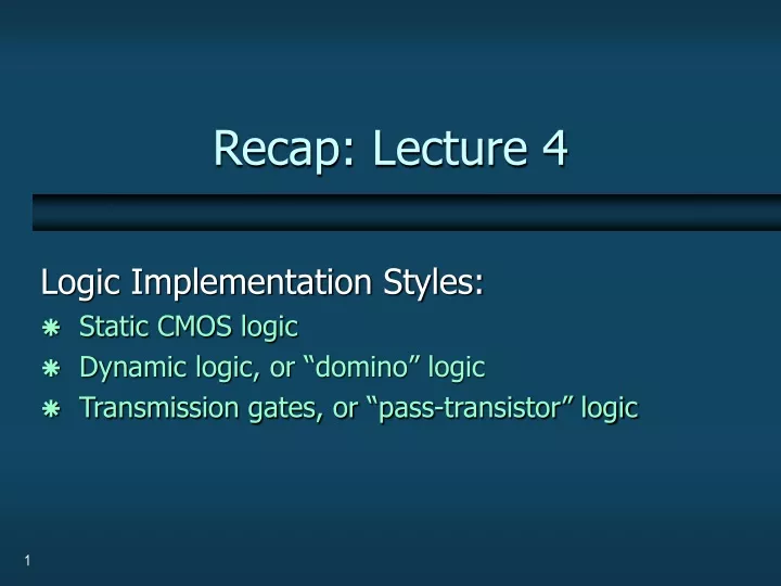
Recap: Lecture 4. Logic Implementation Styles: Static CMOS logic Dynamic logic, or “domino” logic Transmission gates, or “pass-transistor” logic. Static CMOS logic. Advantages: output always strongly driven

E N D
Recap: Lecture 4 Logic Implementation Styles: Static CMOS logic Dynamic logic, or “domino” logic Transmission gates, or “pass-transistor” logic
Static CMOS logic Advantages: • output always strongly driven • pull-up and pull-down networks are fully-complementary;exactly one of them is “on” always • good immunity from noise and leakage • both inverting and non-inverting functions implementable • each gate is inverting • cascade two gates together to get non-inverting logic Disadvantages: • slow/big PMOS devices needed (in addition to NMOS) • greater chip area • higher power consumption • slower switching speed
Dynamic Logic, or “domino” Key idea: • only use NMOS’s to compute function • use a single PMOS to reset Advantages: • significantly fewer transistors smaller chip area • higher speed, lower power • less “loading” on wires (drive fewer transistors) • for async: no storage elements needed Disadvantages: • need extra control input to precharge • logic is typically non-inverting only • more vulnerable to noise and leakage effects
Dynamic Logic, or “domino” (contd.) Gate has 2 phases: • precharge (=reset): output reset to ‘0’ • evaluate: output computed either stays ‘0’, or switches to ‘1’ Pull-up and pull-down must never both be simultaneously active: • ensure that data inputs are reset while gate is precharging • or, add a “footer” device control input controls“precharge” PC PC =0 (asserted) precharge pull-upnetwork pull-down network dataoutput PC =1 (de-asserted) evaluate datainputs controls“evaluation”
Transmission Gates Key Idea: • transistors used in a different configuration • when switched on: instead of connecting output to Vdd or Gnd, they connect output to the input Advantage: • very efficient for implementing switches and multiplexors Disadvantage: • not very useful for logic functions
Lecture 5:A Classic Dynamic Pipeline Williams and Horowitz’s PS0 pipeline: Structure Operation Performance
A Classic Approach: PS0 Pipeline Stage 2 Stage 3 Stage 1 ack Data in Data out data Processing Block Completion Detector Williams/Horowitz (Stanford U.) [1986-91]: • successfully used in fabricated chips [Stanford ’87] [HAL ’90s] Implemented using “dynamic logic”
PS0 Pipeline Stage ack Completion Detector A PS0 stage consists of dynamic gates and a completion detector: PC “keeper” datainputs Pull-down network dataoutputs Processing Block
Dual-Rail Completion Detector bit0 bitn bit1 OR OR OR Done C • Combines dual-rail signals • Indicates when all bits are valid (or reset) C-element: • if all inputs=1, output 1 • if all inputs=0, output 0 • else, maintain output value • OR together 2 rails per bit • Merge results using “C-element”
PS0 Protocol 4 3 indicates “done” 6 5 1 2 3 • PRECHARGE N: when N+1 completes evaluation • delete data:after next stage has copied it • EVALUATE N: when N+1 completes precharging • accept new data: after next stage is emptied indicates “done” indicates “done” N N+1 N+2 precharges evaluates evaluates evaluates Complete cycle: 6 events Evaluate Precharge: 3 events Precharge Evaluate: another 3 events
PS0 Performance 6 4 Cycle Time = 5 1 2 3
Summary: PSO Pipelining Datapaths are latch-free: • dynamic gates themselves provide implicit latches +: chip area savings +: extremely low latency Data items kept separate by control • stage deletes data:only afternext stage has copied it • stage accepts new data:only ifnext stage is empty • distinct data items always separated by “spacers” Control is extremely simple: each controller = single wire • completion detector directly controls previous stage +: chip area savings +: low control overhead
Drawbacks of PSO Pipelining • Poor throughput: • long cycle time: 6 events per cycle • data “tokens” are forced far apart in time • Limited storage capacity: • max only 50% of stages can hold distinct tokens • data tokens must be separated by at least one spacer
Comparison to a Clocked Pipeline latch How would you design the pipeline if you actually had a clock? • Replace handshaking with “magic clocking” • each stage gets its own clock • successive clocks are slightly skewed • essentially, clocked simulation of asynchronous handshaking! – need multiple clock phases! • Use a single clock, but insert latches between stages • latches are simple, level-sensitive • consecutive stages receive complementary clock signals Ck Ck’
Comparison … (contd.) Cycle Times?