Download
1 / 25
260 likes | 437 Views
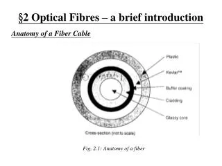
Tutorial on optical fibres. F. Reynaud IRCOM Limoges Équipe optique. Cargèse sept 2002. Silica fibres typical refractive index : 1,45 – 1,50 R efractive index difference Core diameter : 5 à 50 µm Cladding diameter : 125 à 500 µm. 1) Generalities. optical fibre structure.

E N D
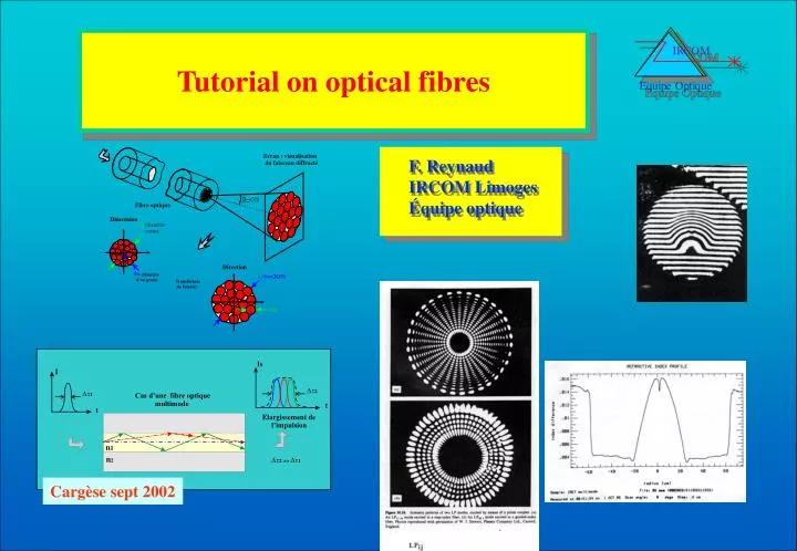
Tutorial on optical fibres F. Reynaud IRCOM Limoges Équipe optique Cargèse sept 2002
Silica fibres typical refractive index : 1,45 – 1,50 Refractive index difference Core diameter : 5 à 50 µm Cladding diameter : 125 à 500 µm 1) Generalities optical fibre structure Refractive index profil Cargèse sept 2002
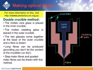
1) Generalities optical fibre manufacturing 1) preform manufacturing 2) Drawing process (Modified Chemical Vapour Deposition). PCVD (Plasma Chemical Vapour Deposition) OVPO (Outside Vapour Phase Oxydation Cargèse sept 2002
2) Propagation in optical fibres Geometrical optics Snell Decartes law : i1 > ilim Possibility to trap light beams in an high refractive index area surrounded by a low refractive index area Cargèse sept 2002
2) Propagation in optical fibres Wave theory First example planar mirror guide For each n one propagation mode Two directions interference between two plane waves Propagation without losses: Intensity =0 on mirrors a = n i with n = integer Cargèse sept 2002
2) Propagation in optical fibres Wave theory Second example Planar dielectric waveguide Two directions interference between two plane waves Propagation without losses: Intensity =0 close to the core/cladding interface a+ 2 e = n i with n = integer One mode n One angle qn solution of the equation Cargèse sept 2002
2) Propagation in optical fibres Wave theory Second example Planar dielectric waveguide solutions q 0 q1 q2 q3 Limited number of mode If only one>>>monomode Cargèse sept 2002
2) Propagation in optical fibres Wave theory 3 D interference Cargèse sept 2002
2) Propagation in optical fibres Wave theory Properties of the modal structure Same transverse field distribution at the input and output Propagation = phase shift bn is the propagation constant Decomposition of any optical field onthe mode basis Propagation = phase shift Cargèse sept 2002
2) Propagation in optical fibres Dispersion b depends upon Modal or intermodal dispersion Mode in a multimode fibre Cargèse sept 2002
2) Propagation in optical fibres 25 20 15 10 Chromatic dispersion (ps/nm.km) G.652 (0.08 ps/nm2.km) 5 0 G.653 EDFA bandwidth -5 G.655 G.655 -10 1200 1300 1400 1500 1600 Wavelength (nm) Dispersion Chromatic or intramodal dispersion Wavelength dependent b=b(l) Cargèse sept 2002
3) Determination of the mode number Monomode beam Diffraction properties Basic rules General case Multimode beam Cargèse sept 2002
3) Determination of the mode number Case of an optical fibre Numerical aperture NA Core diameter l/a Number of spots or speckles Number of modes Cargèse sept 2002
3) Determination of the mode number One speckle surface diameter Fibre core surface diameter a Number of degrees of freedom Warning: N is wavelength dependent Cargèse sept 2002
3) Determination of the mode number Two examples Warning: N is wavelength dependent n1=1.462 n1=1.455 n2=1.450 n2=1.450 a=50µm a=8µm @ l = 1.3µm @ l = 1.3µm Multimode fibre Monomode fibre Cargèse sept 2002
4) Characterisation of optical fibres Numerical aperture Refractive index distribution n(radius) radius Cargèse sept 2002
Launching assembly 1.0 Transmission fibre loss (silica) Fibre length L Loss (dB/km) First step 0.5 Detector 0.2 Launching assembly 0.1 =0 Fibre length d 10001200130014001500 1600 Wavelength (nm) Second step Detector 4) Characterisation of optical fibres Fibre losses I2 I1 Cargèse sept 2002
5) Optical fibre implementation Connectors Plug with a ceramic ferule body FCPC E2000 Loss as function of The transverse position error Cargèse sept 2002
5) Optical fibre implementation couplers From 2 to 2 polishing Glued Fusion splicing From 2 to 8 Cargèse sept 2002
6) Application of optical fibers principal use>> optical fibre telecommunications Very high bit rate 1 Tbit/sec Very low losses The solution for long distance signal propagation Cargèse sept 2002
6) Application of optical fibers Optical fibre sensors Temperature Pressure Rotation Chemical concentration Cargèse sept 2002
6) Application of optical fibers Possibility to built interferometers See next lecture Mach Zehnder configuration Cargèse sept 2002
7) Material and new optical fibers UV 0.3µm Near IR 2µm Far IR 10µm Visible Cargèse sept 2002
Fast PSP DGD Slow PSP 7) Material and new optical fibers Polarisation preserving fibers cladding Propagation core Stress area Highly birefringent fibres Cargèse sept 2002
7) Material and new optical fibres Photonic crystal fibres structure Monomode over a very large spectral domain Cargèse sept 2002