Download
1 / 14
140 likes | 265 Views
Electronics development for fast-timing PET detectors: The multi-threshold discriminator Time of Flight PET system. Contents 1. Introduction 2. Experimental Setup 3. Results 4. Summary. Heejong Kim 3 , Jialie Lin 1 , Octavia Biris 1 , Chin-Tu Chen 3 , Woon-Seng Choong 4 ,

E N D
Electronics development for fast-timing PET detectors:The multi-threshold discriminator Time of Flight PET system Contents 1. Introduction 2. Experimental Setup 3. Results 4. Summary Heejong Kim3, Jialie Lin1, Octavia Biris1, Chin-Tu Chen3, Woon-Seng Choong4, Henry Frisch1,2, Chien-Min Kao3, William Moses4, Fukun Tang2, Qingguo Xie3, Lin Zhou2 1. Department of Physics, University of Chicago, IL 2. Enrico Fermi Institute, University of Chicago, IL 3. Department of Radiology, University of Chicago, IL 4. Lawrence Berkeley National Laboratory, Berkeley, CA
1. Introduction • Digitize PET event waveform and apply digital-signal processing (DSP). • Potential advantages: • allow sophisticated information processing • easy to upgrade • inexpensive, high-performance digital components are common • A promising multi-threshold method is investigated by using digitized event waveforms obtained at a 20GHz sampling rate • Q. Xie, etal, “Potential advantages of digitally sampling scintillation pulses in timing determination in PET,”NSS/MIC 2007, pp. 4271-4274, 2007. Multi-threshold method cf. PMT signal polarity is reversed for display purpose.
Multi-threshold discriminator board Differential outputs • 8 channels/board (4 channels installed): • ADCMP582 SiGe voltage comparator, • 37ps rise/fall time • programmable threshold levels for • individual comparators, adjustable • from 0~-700mV and controlled by • UMDDA-08HC DAC • Each channel provides differential • LVDS outputs (high=1.26V, low=0.94V) • 2 boards are implemented Threshold Setting Input
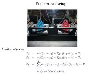
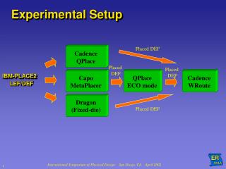
2. Experimental Setup • Three discriminator thresholds: • -100, -200, -300mV. • Tektronix TDS6154C oscilloscope: • 4 input channels • 15 GHz bandwidth • 20GS/s sampling. • Trigger for the oscilloscope • Lecroy 623B discriminator, • Lecroy 365AL coincidence. Block diagram for result B&C PMT Holder from LBL
3. Results A. Time offset and resolution of discriminator boards B. Pulse shape reconstruction Energy resolution Scintillation decay constant C. Timing uncertainty of the multi-threshold method D. Coincidence timing resolution F. Time readout using TDC (HPTDC)
A. Time offset and resolution ofthe discriminator board Comparator 1 Comparator 2 Block diagram for result A Top : comparator outputs Bottom: Zoom in of the leading edge
A. Time offset and resolution ofthe discriminator board (Cont’d) board#1 Dt (ps) s (Dt) ch1-ch2 194.9 7.2 ch1-ch3 404.8 7.6 ch1-ch4 613.6 8.4 board#2 ch1-ch2 209.5 7.1 ch1-ch3 414.8 7.8 ch1-ch4 630.4 8.0 Ch4 is the closest to the input DT( ch1-ch2) • Measurements used to correct time offset between channels • Time resolution of single channel was estimated to be ~13ps (FWHM)
B. Pulse shape reconstruction • use three thresholds: • -100, -200 and -300mV • time-offset correction applied • reconstruct pulse shape using 6 time measurements • linear fit on the leading • exponential fit on the falling Blue: PMT signal Red: multi-threshold timing, time-offset corrected Bottom : Zoom in of the leading part
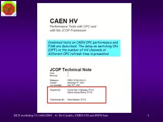
B. Energy resolution • Pulse height: • 20Gs/S waveform: sample sum • multi-threshold: area under reconstructed curve • Energy resolution: • multi-threshold: 18% • 20Gs/S waveform: 13% Integrated charge
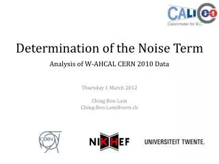
B. Decay constant • exponential fit on the tail gives the decay time constant • Results: mean: 43ns vs. 47ns • width (FWHM): • 14ns vs. 4ns Decay constant
C. Timing uncertainty of the multi-threshold method (1) (2) Dt(1-2) 49ps FWHM
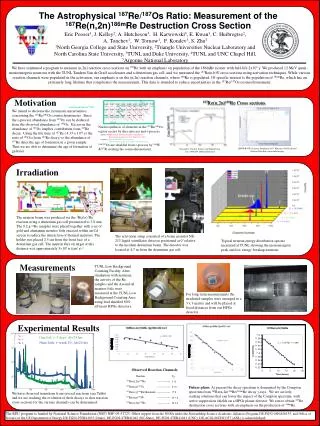
D. Coincidence timing resolution 332ps FWHM Differential time The differential time has a 332ps FWHM cf. Timing resolution of ~300ps using CFD discriminator (Q. Xie et al. NSS/MIC 2007, p4271)
D. Time readout using HPTDC Sample output from HPTDC HPTDC board (LBL) multi-threshold board • 4 thresholds: • -100, -200, -300, -400mV • time-offset applied • consistent with above results
Summary • Multi-threshold discriminator boards with adjustable thresholds developed and evaluated • Time offset between comparator channels measured and corrected; timing resolution of a single comparator: ~13ps (FWHM) • Tested with LSO+R9800PMT and Na-22 • reconstruct event pulse using time outputs of the discriminators • 18% energy resolution at 511keV obtained by using 3 thresholds (-100mV, -200mV and -300mV), compared to 13% by using the full PMT waveform • the use of the multi-threshold method with three thresholds estimated to contribute a timing uncertainty of ~49ps FWHM. • A 332ps FWHM coincidence timing resolution obtained by using 2 thresholds (-100mV and -300mV), compared to ~300ps when using a CFD • Initial successful results with HPTDC obtained