Download
1 / 12
120 likes | 419 Views
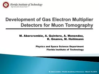
Prototypes For Particle Detectors Employing Gas Electron Multiplier. J. Slanker, G. Karagiorgi, F. Plentinger, K. Dehmelt, M. Hohlmann, L. Caraway Florida Institute of Technology Physics and Space Science. GEM Foils . GEM (Gas Electron Multiplier) - 3M Worldwide

E N D
Prototypes For Particle Detectors Employing Gas Electron Multiplier J. Slanker, G. Karagiorgi, F. Plentinger, K. Dehmelt, M. Hohlmann, L. Caraway Florida Institute of Technology Physics and Space Science
GEM Foils GEM (Gas Electron Multiplier) - 3M Worldwide - copper coated Kapton foil - 60 mm holes - 140 mm apart - 1 in. active area 1 in. J. Slanker - FAS 2004
GEM Foils - Potential Difference across each GEM foil (300 V – 500 V) F. Sauli - High energy particles ionize the gas inside the detector which drift to the GEM foil - Electric field through the holes causes the electrons to cascade F. Sauli J. Slanker - FAS 2004
Single GEM Detector 5mm Spacer Drift Plane - All materials must have Negligible Out-Gassing Drift Plane – Copper Coated G10 PC Board Spacers – PeeK (Poly Ether Ether Ketone) Induction Plane GEM foil 2mm Spacer Florida Tech Single GEM Version 1.0 J. Slanker - FAS 2004
Single GEM Detector Setup - 9mm thick Plexiglas box 50x50x10 cm - Stainless Steel Tubing - Swagelok stainless steel fittings - 70:30 Ar/CO2 Gas environment Observations - Large, irregular pulses found (Cosmic Rays or Discharge) - Frequency increased over time - No pulse change with source - Disassembled detector found damage near solder points Initial GEM conditions - 2.5 kV total bias - 400 V potential difference across the GEM foil J. Slanker - FAS 2004
Single GEM Detector Modifications - BNC for signal output - 500 V Potential Difference across GEM - Hole drilled through Drift Plane covered with Mylar foil - Electric Fields within Drift Gaps changed to match recommendations of F. Sauli, CERN J. Slanker - FAS 2004
Single GEM Detector Signal from Florida Tech Single Gem - Acquired using National Instruments fast oscilloscope card - Count rate consistent with Cosmic Ray muon flux - However, no noticeable count rate change when using Fe55 source - Most likely still sparking within in the GEM detector J. Slanker - FAS 2004
Triple GEM Detector - Design and Fabrication began as soon as the single GEM was complete - Learning from old mistakes and using new ideas - Pressed brass rings on either side of the GEM foil to apply High Voltage - Makes the detector more gas tight - Prevents damage from soldering iron and sparking due to solder points J. Slanker - FAS 2004
Triple GEM Detector GEM Foil Assembly J. Slanker - FAS 2004
Triple GEM Detector Top Assembly J. Slanker - FAS 2004
Triple GEM Detector Final Assembly Future Plans - assemble - use Fe55 source to find pulse height spectra - compare our detector performance to others - study aging in GEM detectors - use for high energy physics/ astrophysics research J. Slanker - FAS 2004
Acknowledgements Out-gassing Information http://outgassing.nasa.gov/ GEM Graphics (order of appearance) L. Caraway F. Sauli K. Dehmelt G. Karagiorgi F. Plentinger J. Slanker - FAS 2004