Download
1 / 10
100 likes | 106 Views
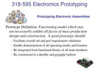
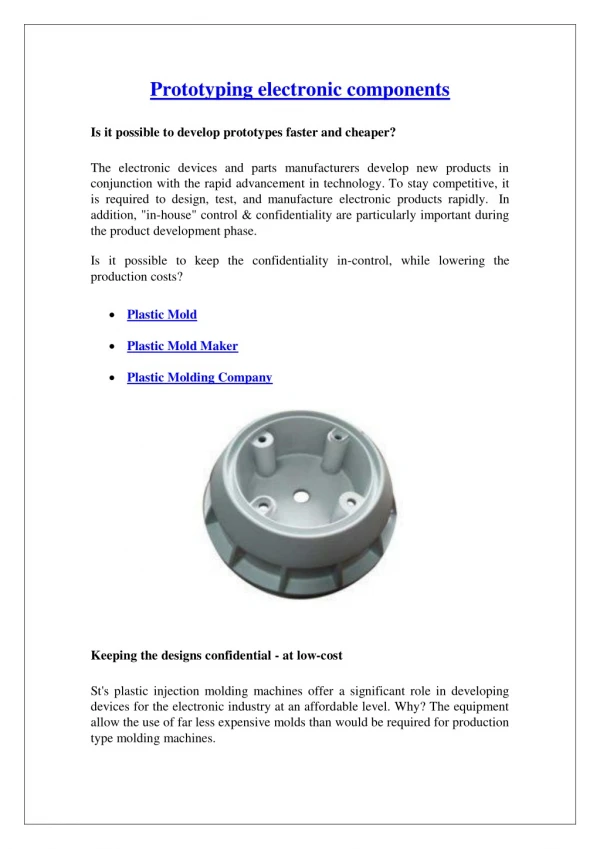
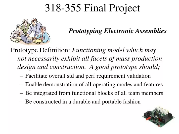
Prototyping Electronic Assemblies. Prototype Definition: Functioning model which may not necessarily exhibit all facets of mass production design and construction. A good prototype should; Facilitate overall std and perf requirement validation

E N D
Prototyping Electronic Assemblies Prototype Definition: Functioning model which may not necessarily exhibit all facets of mass production design and construction. A good prototype should; • Facilitate overall std and perf requirement validation • Enable demonstration of all operating modes and features • Be integrated from functional blocks of all team members • Be constructed in a durable and portable fashion
Project Prototyping Plan • Partition the Electronics, Determine # of Circuit Bds Considerations • Functional Separations, Block Separations, Displays & User I/O • Power Supply or Safety Circuits from Analog or Digital • EMC and ESD protections • RF Circuits and Shielding • Power and Heat Dissipation, Heat Sinks, Fans, Cooling • Battery attachments and compartments • Total path length and “inductance” from power source(s) • Total surface area of components • For each design “block”, Determine: • For each unique part, footprint area including mounting • Total area of design block prototype parts • Total area for each circuit board required
Project Prototyping Plan • Determine the type(s) of circuit boards • Cu Laminate “Etched” • Direct Transfer • Photo Transfer • Pre-Perforated Boards • Plastic, no pads, no busses • Plastic, pads, no busses • Plastic, pads, busses • Flat Insulating Substrate • Bread Board
Project Prototyping Plan • Determine the type(s) of component attach • Direct Solder or IC Socket • For Cu PCB or Perf Boards • Adapters for SMT • Wirewrap Socket • For Cu PCB or Perf Boards • Mechanical Attachments
Project Prototyping Plan • Determine the type(s) of interconnection, tools required per board • Solid Wire Solder Connection • Use #18-22AWG for power • Solder all connections • Wirewrap #30 AWG • For small signal connections • Less than 25 mA • No Soldering Necessary
Project Prototyping Plan • Determine the type(s) of interboard connections • Parallel or Buss Connections • Ribbon Cable, Headers • Power Connectors • NEC, IEC320, DC, Molex • Individual Signal Connectors • Audio: RCA, Motorola • Video, RF: BNC, F, N, S, SMA/B • Telecom: Sub-D, RJ-11, RJ45, USB
Project Prototyping Plan • Determine the overall enclosure types and numbers; • Metal Enclosures (Provide Shielding, Grounding) • Plastic Enclosures (Provide Durability, Workability, Impact Resistance, Insulation, Matched with Displays) • Both are available in numerous off-the-shelf products
Popular Distributor URL’s • http://www.radioshack.com • http://www.jameco.com • http://www.alliedelec.com • http://www.digikey.com/ • http://www.marshelectronics.com/ • http://www.e-d-c.com/ • http://www.jacoelectronics.com/ • http://www.bellmicro.com/linecards/Belllinecard.asp • http://www.unionel.com/catalog/catalog_index.html • http://www.newark.com/ • http://www.futureelectronics.com/ • http://www.mouser.com/ • http://www.eneumann.com/ • http://www.garrettelec.com/ • http://www.rell.com/ • http://www.route22electronics.com/ • http://www.lauralekx.com/ • http://www.abra-electronics.com/ • http://lookic.com/ • http://www.mpja.com/
Popular Distributor URL’s • http://www.sager.com/ • http://www.simcona.com/ • http://www.cornell-dubilier.com/distframe.htm • http://www.arrow.com/ • http://www.pcipci.com/ • http://www.newyorkerelectronics.com/ • http://www.carlton-bates.com/ • http://www.trendsetter.com/ • http://www.mpaqelectronics.com/ • http://www.camrpc.com/ • http://www.walkercomponent.com/ • http://www.brotherselectronics.com/ • http://www.ceewesco.com/ • http://www.rselectronics.com/ • http://www.hammondelec.com/ • http://www.azcomponents.com/ • http://www.ahmtec.com/ • http://www.web-tronics.com/
Prototyping: Soldering • Wire Solder types: • Solid Core: Mixture of ~60%Sn, ~40%Pb (Pb free by 2006/8) • Acid Core (Not for electronics) • * Flux Core (Rosin paste) • Solder Iron Types: • * Pencil (AC powered) w/o temp control (15-30 Watts) • Pencil (AC powered) with temp control (variac) • Gun (AC powered) with temp control (used for larger applications) • LP pencil or gun (Butane or LP powered) • Soldering Tips are usually detachable/replaceable, must be kept clean by using a wiping system (damp sponge or rag). When fully powered, many soldering devices will ignite paper, wood and other combustables …… caution • Soldering should be done on a non-combustable surface • The iron is used to heat the metal parts that are to be joined by surface contact. • The tip of the iron should be solder “wetted” in order to transfer heat to the parts more efficiently with the surface contact. • The wire solder is then touched to the side opposite to the heat application. If of sufficient temperature, the solder will melt and “flow” toward the heat source. • All metal surfaces to be joined need to be clean. If coated with any corrosion or oils, the process will not work or be prone to early failures Solder Pump Removal Tool Cold Solder Joints