Download
1 / 15
150 likes | 359 Views
Cross Layer Design of Heterogeneous Virtual MIMO Radio Networks with Multi-Optimization. Wei Chen*, Heh Miao, Liang Hong, Jim Savage, Husam Adas Dept. of Computer Science Tennessee State University, USA Supported by AFRL APDPM 2010. Outline. Introduction to MIMO &Virtual MIMO Technology

E N D
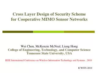
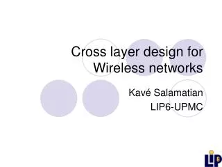
Cross Layer Design of Heterogeneous Virtual MIMO Radio Networks with Multi-Optimization Wei Chen*, Heh Miao, Liang Hong, Jim Savage, Husam Adas Dept. of Computer Science Tennessee State University, USA Supported by AFRL APDPM 2010
Outline • Introduction to MIMO &Virtual MIMO Technology • Problem Statement • Cross-Layered Design of Virtual MIMO Radio Networks • Virtual MIMO Network Modeling • Cooperative Communication Schemes • Formation/reconfiguration of Virtual MIMO networks • Routing Backbone and Protocols • Testing and Evaluation • Summary and Future Work
diversity gain multiplexing gain Introduction to Virtual MIMO technology MIMO Technology Without using extra energy and channel, a MIMO transceiver can be used to • Extend communication range or reducing error rate (diversity gain) • Provide higher data rate (multiplexing gain) MIMO transceiver Wireless MIMO network However, it is unrealistic to equip multiple antennas to small and inexpensive wireless devices (e.g., crossbow sensor nodes).
one 4×2 MIMO link one 2×3 MIMO link Introduction to Virtual MIMO technology Cooperative Communication/ Virtual MIMO Technology • Distributed individual single-antenna nodes cooperating on information transmission and reception as a multiple antenna array B C A Other hops First hop
Problem Statement Previous Works • Communication Schemes: MIMO scheme, MISO scheme • Architecture of Virtual MIMO Network: Homogeneous – the size and diameter of each virtual MIMO node are same, the distance between of virtual MIMO nodes are the same. It is possible only when the cooperative nodes are manually deployed and the topology never changes. (Reference [7,8]) This Research Design of heterogeneous virtual MIMO network including cooperative communication scheme, formation and reconfiguration of virtual MIMO network and routing protocol to leverage MIMO technology in a cross-layer fashion to optimize latency, energy consumption, QoS and network lifetime.
MIMO Link MISO Link 3×2 MIMO link SIMO Link SISO Link Virtual MIMO Network Modeling • Underlying network: Network G = (V,E) of single-antenna radio nodes. • d-Clustering: A node disjoint division of V, where the distance between two nodes in a cluster is not larger than d. The clusters are called virtual MIMO nodes, and the nodes of G are called primary nodes. • D-Virtual-MIMO links: Let A and B be two d-clusters, and A’ and B’ be the subsets of A and B, respectively. Suppose there are mt nodes in A’ and mr nodes in B’. If the largest distance between a node of A’ and a node of B’ is not larger than D, a D-mt×mr virtual MIMO transmission link can be defined between A and B. According to mt = mr = 1, mt > 1 and mr = 1, mt = 1 and mr >1, mt > 1 and mr > 1, the virtual MIMO link is called SISO link, MISO link, SIMO link and MIMO link, respectively. • Heterogeneity: The number of primary nodes in the cluster, the diameter of a cluster, and the length of virtual MIMO links can be different.
Cooperative Communication schemes – Design C B A Other hop First hop • Proposed Multi-MISO Scheme d three 4×1 MISO links three 4×1 MISO links B A B C D Other hops First hop Step 1 (Local transmission at A):Each node i in A broadcasts information to all the other local nodes using different timeslots. Step 2 (long-haul transmission between A and B):Each node i in A acts as the ith antenna encoding the sequence using the mt×1 MISO code system. All mt nodes in A broadcast encoded sequence to the nodes in B at the same time. Each node of mr nodes in B receives mtencodedsequences, and then decodes them back to according to the mt×1 MISO code system. • MISO Scheme (Yuan) • MIMO Scheme (Cui et al) one 4×2 MIMO link one 3×1MISO link one 2×3 MIMO link one 3×1 MISO link B C A D Other hops First hop
Cooperative Communication schemes – Evaluation constellation size Energy consumption and Latency for Multi-MISO scheme
Cooperative Communication schemes – Evaluation First hop Other hops
Formation/Reconfiguration of Virtual MIMO networks –formation of virtual MIMO nodes Algorithm 1Formation of d-Clusters Input:Network G = (V,E) of single-antenna radio nodes, and communication range d/2. Output: node-disjoint clusters; the diameter of clusters is not larger than d. Each node u executes the following rounds: Round 1:u broadcasts its ID, and receives the IDs from its neighbors. Round 2: (1) u selects a node v with the smallest ID in the received IDs to be u’s CH. (2) u transmits head declare message (u, v, “head-declare”) to v, and receives the head declare messages from its neighbors. Round 3: (1) In the received messages, if u finds any neighbor v who declares u as v’s CH, u sets itself as a CH abd adds v to its member-list. (2) If u is a CH, it broadcasts message (u, “head-confirm”), and (3) u receives the head-confirmation messages from its neighbors. Round 4: If u received messages (v, “head-confirm”) and v is in u’s member-list, u removes v from u’s member-list.
Formation/Reconfiguration of Virtual MIMO networks –formation of routing backbone Algorithm 1Formation of Routing Backbone (Spanning tree of head nodes) Input:mCHs, a sink s, and transmission range D Output: A spanning tree of the m CHs with the sink as the root; the distance between two neighboring CHs in the backbone is not larger than D. Sink s executes the following rounds (finding the children): Round 1: s broadcasts (s, “find children”), changes its status to “reception”, and receives the responses. Round 2: If s receives message (u, s, “child”), s adds each u to its children list; Other node u executes the following rounds (Selecting the parent and finding the children) (1) If u received (v, “find children”) from nodes v and u hasn’t decided the parent yet, then u selects one node w from those nodes to be u’s parent; (ii) u transmits (u, w, “child”) to w ; (iii) u broadcasts (u, “find children”). (2) If u has selected the parent and u received messages (v, u, “child”), u adds v to u’s children list.
Link jumping Head rotation Formation/Reconfiguration of Virtual MIMO networks – Reconfiguration Algorithm 3 Head-Rotation (u: CH node, e: energy threshold, d: transmission range in clusters) u checks its battery energy; if u’s energy level is lower then u selects a CMv from its cluster which has the largest energy level; u broadcasts a head-rotation request “new head is v” using transmission distance d; when v received the request and information from u, v changes its status to be CH, and delete u from its member list; when u’s any other member w received the request from u, w changes v to be its CH. Algorithm 4Link-Jumping (u: CH node) u broadcasts a link-jumping request with the ID of u’s parent v and transmission range of u and v using transmission range max{d(u,x) | x is u’s backbone neighbor and d(u,x) is the transmission range of u and x}. When u’s any child w receives the Link-jumping request, w sets u’s parent v to be the parent, and sets the transmission distance from w and v to be d(w,v) = d(w,u)+d(u,v).
Underlying network: single-antenna nodes are randomly deployed in 400m×400m fieldAverage size of virtual MIMO nodes: 2 – 4 Diameter d of virtual MIMO nodes: 2m – 10 m Bandwidth: 10 k – 20k Transmission range D of virtual MIMO links: 50m – 150mTask: four source data with 20K bit each are relayed back to the sinkComparison: Energy consumption and latency in schemes of Chen, Cui, Yun and traditional (tra) non-cooperative approaches, respectively. Testing and Evaluation
Conclusion and Future works Summery • Multi-MISO scheme minimizes the intra communication in virtual MIMO nodes. It saves energy and reduces latency simultaneously. • Virtual MIMO nodes/links are allowed to be heterogeneous in order to apply the visual MIMO technology to any single-antenna radio network. • The proposed routing backbone simultaneously optimizes energy and latency along the route. • The network is reconfigurable with low cost. Future work • The proposed virtual MIMO network is reconfigurable. It shall have a very long network lifetime comparing with other virtual MIMO networks. We leave the evaluation to the future work.
Homework and assignment • There are two clustering approaches: star-graph based clustering and complete-graph based clustering. Discuss the tradeoff on backbone size, latency, and efficiency of architecture reconfiguration, respectively. • In this research, the cluster-based architecture doesn’t use gateway nodes (cluster heads connected with cluster heads). Does it make sense and why? • Find the application of multiple antenna array (smart antenna) in daily life.