Download
1 / 1
10 likes | 117 Views
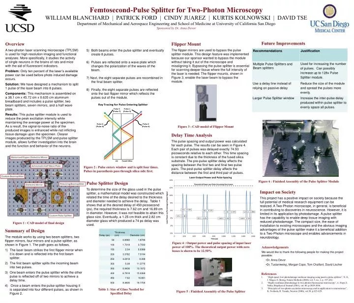
Femtosecond-Pulse Splitter for Two-Photon Microscopy WILLIAM BLANCHARD | PATRICK FORD | CINDY JUAREZ | KURTIS KOLNOWSKI | DAVID TSE Department of Mechanical and Aerospace Engineering and School of Medicine at University of California San Diego Sponsored by Dr. Anna Devor.

E N D
Femtosecond-Pulse Splitter for Two-Photon Microscopy WILLIAM BLANCHARD | PATRICK FORD | CINDY JUAREZ | KURTIS KOLNOWSKI | DAVID TSE Department of Mechanical and Aerospace Engineering and School of Medicine at University of California San Diego Sponsored by Dr. Anna Devor Future Improvements Overview A two-photon laser scanning microscope (TPLSM) is used for high resolution imaging and functional analyses. More specifically, it studies the activity of single neurons in the brains of rats and mice with the aid of fluorescent indicators. Problem: Only ten percent of the laser’s available power can be used before photo induced damage occurs. Solution: We have designed a mechanism to split 1 pulse of the laser beam into 8 pulses. Components: This mechanism is assembled on a 38.1 cm x 45.72 cm x 0.635 cm aluminum breadboard and includes a pulse splitter, two beam splitters, seven mirrors, and a half wave plate. Results: This pulse splitter module is used to reduce the peak excitation intensity while maintaining the average power at the specimen. As a result, the signal-to-noise ratio of the produced images is enhanced while not inflicting tissue damage upon the specimen. Clearer images produced by the TPLSM and pulse splitter module, allows further investigation into the brain and the function and behavior of the neurons. Flipper Mount The flipper mirrors are used to bypass the pulse splitter module. This design feature was implemented because our sponsor wanted to bypass the module without taking it out of the microscope and misaligning it. Bypassing the pulse splitter is essential for scanning deeper tissue where the full intensity of the laser is needed. The flipper mounts, shown in Figure 3, enable the laser beam to bypass the module. • Both beams enter the pulse splitter and eventually create 8 pulses. • 6) Pulses are reflected onto a wave plate which changes the polarization of the waves of the beam. • 7) Next, the eight separate pulses are recombined in the final beam splitter. • 8) Finally, the eight separate pulses are reflected onto the last flipper mirror which reflects the pulses out of the module. Figure 3 : CAD model of Flipper Mount Delay Time Analysis The pulse spacing and output power was calculated for each pulse. The results can be seen in Figure 4. Each pair of pulses was delayed exactly 74.93 picoseconds relative to each other. This time spacing is constant due to the thickness of the fused silica substrate. The pre-pulse splitter delay affects the spacing between the first two and final two pulse pairs. The post-pulse splitter delay affects the distance between the first and third pair of pulses. Figure 2 : Pulse enters window and is split four times. Pulses in parenthesis pass through silica side first. Figure 6 : Finished Assembly of the Pulse Splitter Module Pulse Splitter Design To determine the size of the glass used in the pulse splitter, a mathematical model was constructed which related the time of the delay desired to the thickness and diameter needed to achieve the delay. Table 1 shows that at the desired delay of 450 picosecond (ps), the required thickness is 7.62 cm and 16.89 cm in diameter. However, it was not feasible to attain this glass size. Eventually, a 1.25 cm thick and 2.82 cm diameter glass which produced a 74 ps delay was used. Impact on Society This project has a positive impact on society because the full potential of medical research equipment can be realized. A Two-Photon microscope, in general, is beneficial in contributing to discoveries in neuroscience. However, it is limited in its application by photodamage. A pulse splitter has the capability to enable deep tissue imaging with reduced photodamage. The compact size, the ease of installation to existing microscopes and the obvious imaging advantages of the pulse splitter make it a beneficial addition to a Two-Photon microscope and enables advancements in neurobiology. Figure 1 : CAD model of final design • Summary of Design • The module works by using two beam splitters, two flipper mirrors, four mirrors and a pulse splitter, as shown in Figure 1. The path goes as follows. • The laser beam strikes the first flipper mirror when it is down and is reflected into the first beam splitter. • The first beam splitter splits the incoming beam into two pulses. • One beam enters the pulse splitter while the other pulse is reflected off of two mirrors to achieve a delay time. • Once a beam enters the pulse splitter housing it is separated into four different pulses, as shown in Figure 2. Figure 4 : Output power and pulse spacing of input laser power of 100%. The theoretical output power with zero losses is shown to be 12.50% • Acknowledgements • We would like to thank the following people for making this project possible: • Dr. Anna Devor • Dr. Tustaniwskyj, Morgan Cope, Tom Chalfant, David Lischer • References • “High-speed, low-photodamage nonlinear imaging using passive pulse splitters”, N. Ji, J. Magee, E. Betzig, Nature Methods (2008), vol. 5, no. 2, p. 197-202. • “Highly nonlinear photodamage in two-photon fluorescence microscopy”, A. Hopt, E. Neher, Biophysical Journal (2001), vol. 80, p.2029-2036. • “Principles of two-photon excitation microscopy and its application to neuroscience”, K. Svoboda, R. Yasuda, Neuron (2006), vol.50, p.823-829. Table 1: Size of Glass Needed for Specified Delay Figure 5 : Finished Assembly of the Pulse Splitter