Download
1 / 30
300 likes | 512 Views
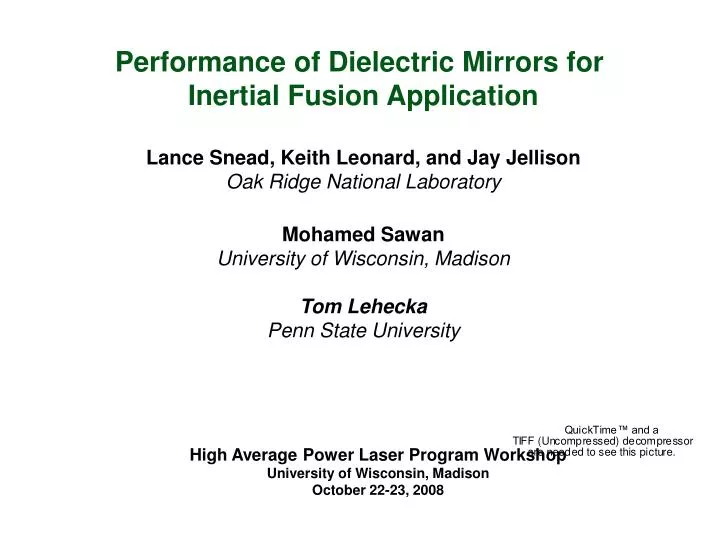
Performance of Dielectric Mirrors for Inertial Fusion Application Lance Snead, Keith Leonard, and Jay Jellison Oak Ridge National Laboratory Mohamed Sawan University of Wisconsin, Madison Tom Lehecka Penn State University. High Average Power Laser Program Workshop

E N D
Performance of Dielectric Mirrors for Inertial Fusion Application Lance Snead, Keith Leonard, and Jay Jellison Oak Ridge National Laboratory Mohamed Sawan University of Wisconsin, Madison Tom Lehecka Penn State University High Average Power Laser Program Workshop University of Wisconsin, Madison October 22-23, 2008
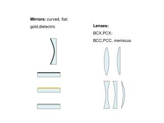
Substrate Background : Dielectric Mirrors • Mirrors are composed of alternating layers of a high and low refractive index films deposited on a substrate. The path difference between the thinner high index films and the thicker low index films results in constructive interference of the reflected light. • Mirrors is tailored to achieve high reflectivity in a specific wavelength band. • Ultra-high reflectivity (>99%), as compared to metal mirrors in the UV range: • Aluminum (80-90%) • Molybdenum (50-60%) • Tungsten (40-50%) • Silver and Gold (<40%) The reflectivity (R) of a lossless multilayer stack of N successive quarter wave layers of alternating high (nHi) and low (nLi) refractive index. High refractive index layer Low refractive index layer
Bio-Shield Shield Focusing (M2) Blanket Turning (M3) GIMM (M1) Beam Duct Geometrical Model Used in 3-D Neutronics Analysis
M2 M3 Flux (n/cm2s) SiC GIMM Fast Neutron Flux Distribution in Final Optics of HAPL .02 dpa lifetime .0003 dpa lifetime 1.0 dpa 2 year
Background: Neutron Irradiation of Dielectric Mirrors Differing opinions as to the use of dielectric mirrors in nuclear environments. E.H. Farnum et al. (1995) • HfO2/SiO2, ZrO2/SiO2, and TiO2/SiO2 mirrors on SiO2 substrates. • Neutron fluence: 1019 n/cm2, 270-300ºC. • Excessive damage in HfO2/SiO2 and ZrO2/SiO2 mirrors, including flaking and crazing of films. Orlovskiy (2005) • TiO2/SiO2, ZrO2/SiO2 mirrors on KS-4V silica glass. • Neutron fluence: up to 1019 n/cm2, 50 ºC. • Dielectric mirrors showed no significant damage under irradiation, mirrors were severely damaged upon annealing (crazing.) Observations and opportunity ? • Fewer and thinner bi-layers may improve resistance to radiation and thermal effects. • Poor performance from SiO2 substrates may be limiting performance; suggested use of more damage resistant substrates (eg: sapphire.) • Damage resistance is sensitive to quality/purity of materials. Explore very high purity.
HAPL Irradiation : Test Samples • Test samples consisted of 3 dielectric mirror types along with single-layer films to evaluate film / substrate interactions. • Higher damage tolerant sapphire substrates used instead of SiO2. • Films deposited by electron beam with ion-assist; Spectrum Thin Films Inc. • GE-124 fused silica bars included in test matrix.
Neutron Irradiation Fused silica mirror SiC TM • 3 samples of each mirror, monolayer and substrate irradiated to 0.001, 0.01 and 0.1 dpa • One order higher than Farnum and Vukolov • Factor of five higher than HAPL M2 mirror • Irradiation temperature 175-200°C
Post Irradiation Examination and Testing • Visual inspection. Signs of delamination, cracking or flaking. • Measurement of relative specular reflectance. Perkin Elmer, Lamda 900 photospectrometer, equipped with 6º relative specular reflectance accessories. Measurements were made on the dielectric mirrors relative to an aluminum mirror standard. • Thermal annealing treatment. 300 and 400ºC, 1.5 hrs with 3ºC/min heating/cooling rate Vacuum <1x10⁻⁶ torr. Density of bars by density gradient column.
Visual Inspection of Neutron Irradiated Samples • Changes in color are observed with increasing neutron exposure. • Highest dose samples nearly opaque to visible light. • Some annealing of color centers observed following thermal treatments. • No visible signs of cracking or delamination. • Slight speckling appearing on some annealed samples: no correlation between temperature, dose or material type. • Unirradiated controls are all clear to visible light. controls 0.001 dpa 0.01 dpa 0.1 dpa
Visual Inspection of Neutron Irradiated Samples • Compared to Vukolov study, current material is quite stable upon post-irradiation thermal annealing. controls 0.001 dpa 0.01 dpa Vukolov 2005 0.1 dpa Substrate KS-4V Fused Silica TiO2/SiO2 layers
Fused Silica Bar Samples Amorphous SiO2, through gamma or neutron irradiation rapidly densifies. Annealing will recover both dimension and refractive index.
Stress Induced in Dielectric Mirrors SiO2 SiO2 HfO2 HfO2 Al2O3 Al2O3 sapphire • Sapphire was chosen as a substrate for it relatively stable performance under irradiation: relatively small swelling, and shallow temperature dependence • Assumption: by closely matching irradiation-induced dimensional change of substrate and layers, induced stress will be minimized, increasing lifetime. • However, we don’t know the irradiation performance of these microcrystalline or amorphous materials.
248 Optical Property Changes: HfO2 / SiO2 mirrors • Gradual shift in or peak reflectivity range to lower wavelengths with dose. • Limited effect at 0.01 dpa. • Maximum reflectivity measurement may have a systematic error due to use of limiting aperture (due to small sample) on the normal spot size of the spectrometer.
Optical Property Changes HfO2 / SiO2 mirrors Neutron Irradiation Effects • Slight shift in working range, little or no reduction in reflectivity. Annealing Effects • Shifting of peak reflectivity range to lower wavelengths occurring with increasing annealing temperature. • Shifting observed in both irradiated and control materials. • Spectra of 0.1 dpa irradiated mirror annealed at 400ºC suggests considerable damage to mirror.
Optical Property Changes: Al2O3 / SiO2 mirrors 248 • Doses up to 0.01 dpa resulted in a peak shift to slightly higher wavelengths. • Reflectance spectra exhibits limited change with dose.
Optical Property Changes Al2O3 / SiO2 mirrors • Irradiation Effects • Relatively small amount of change measured of all mirror types. • Annealing Effects • Annealing resulted in limited shifting of the peak reflectivity as compared to other mirror types. • Differences between 300 and 400ºC annealing diminishes with increasing dose. • A significant loss in reflectivity with 400ºC annealing is possible (further evaluation underway.)
Optical Property Changes: Al2O3 / HfO2 mirrors 248 • Peak reflectivity of as-received mirrors were off-specifications. • No significant change in reflectance spectra to 0.01 dpa. • Lower wavelengths shift observed following irradiation to 0.1 dpa.
Optical Property Changes: Al2O3 / HfO2 mirrors • Neutron Irradiation Effects • No significant change in reflectance curves to 0.01 dpa. • Annealing Effects • Mirror type appears more stable to thermal anneal than that of other mirror types examined.
Summary • Samples exposed up to 0.1 dpa with and without thermal annealing at 300 and 400ºC show no signs of delamination or cracking. • Mirrors show no significant degradation in reflectance up to doses of 0.1 dpa, with shifts in the peak reflectance curve of up to 10 nm towards lower wavelengths occurring at higher doses. • Of the materials studied, the HfO2/SiO2 mirrors show the most sensitivity to radiation dose and thermal effects despite having the fewest number of film layers. • Reflectance spectra of Al2O3 / HfO2 mirrors appear least sensitive to radiation and combined radiation + annealing. • Stability and matched behavior of constituent materials, low number of film layers?
Implication for HAPL • The initial poor performance and resulting dismissal of dielectric mirrors as unstable in reactor environments appears unfortunate and misguided. • The combination of a more stable substrate (sapphire,) combined with higher quality materials, and the selection of more behavior matched materials under irradiation appear to have led to more stable materials. Farnum(95) : glass substrate, glass/ceramic layers, failed by 0.01 dpa Vukolov (2005) : fused silica substrate glass/ceramic layers, failed by 0.01 dpa This Work : sapphire substrate, glass/ceramic and ceramic/ceramic, ok to 0.1 dpa • Results of this work, while preliminary, are encouraging for use of dielectric in HAPL - HAPL first mirror (assumed dielectric), lifetime dose is 0.03 dpa, appears ok. - HAPL final mirror (assumed grazing incidence metal mirror), has substantially flux. Its 2-year dose is approximately 1 dpa. Suggests possibility of dielectric.
Future Work Optical Testing • Spectrophotometer – further evaluate absolute reflectance of films through transmission technique (may not be possible on high dose samples) • Ellipsometry – evaluate film thickness changes in single-layer deposited samples. • Carry out LIDT of non-irradiated mirrors, if results are acceptable, carry out irradiated testing. Structural Characterization • X-ray diffraction analysis. • Cross-sectional transmission electron microscopy. • Raman microprobe – evaluate interfacial strains at interface. Higher Dose Irradiation • Complete irradiation to 1 dpa (2 year assumed limit for GIMM) and 3 dpa. • Include representative bulk materials for bulk property measurement.
Silica densified 0.77% 20.02±0.01mm
Substrate: Silica glass KS-4V, 25 x 2 mm
Neutron Irradiation In result the reflectivity bandsof LT8 and LT9 shifted towards short wavelengths, the spectra of other samples remained unchanged. The samples were inserted in two hermetic aluminium containers which then were filled with He gas. Irradiation was performed in the water-pool nuclear reactor IR-8. The fast neutron fluences were measured by accompanying iron films of isotope Fe54 enriched to 99,92%.
Thermal Tests Heating regimes in Vacuum and Atmosphere Coatings of all Lytkarino samples were damaged during heating. Podolsk samples kept their coatings and optical properties Reflectivity bands of all mirrors shifted towards short wavelengths in heated state ~2 nm / 10C. Working range of Lytkarino samples remained shifted at 2 nm after getting colder
Expected IFE Mirror Irradiation Environment Expected doses: • Total neutron flux to mirror: ~ 2.2x10¹³ n/cm2s (first mirror) to 1x10¹¹n/cm2s (final mirror) • Total neutron fluence in IFE in one year, assuming 80 % plant availability: About 7.2 x 10¹⁷n/cm2 per FPY (first mirror), ~0.02 dpa for 30 year lifetime About 4.4 x 10²⁰n/cm2 per FPY (final mirror), ~ 1 dpa in 2 years Effects on mirrors: • Differences in radiation and thermally induced swelling or contraction of the film layers. • Changes in surface roughness. • Radiation / thermally induced structural changes within a given layer. • Radiation / thermally induced mixing or formation of interlayer compounds. • Reduction in peak reflectivity and shift towards lower wavelengths.