Download
1 / 19
200 likes | 218 Views
Mechanics of Materials(ME-294). Lecture 4: Shear Stress and Strain. Shear Force and Stress.

E N D
Mechanics of Materials(ME-294) Lecture 4: Shear Stress and Strain
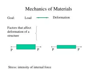
Shear Force and Stress • Imagine a tall stack of coins glued together on their faces. If you pull on the ends of the stack, the glue will experience a stress that is normal (perpendicular) to the face of each coin. This stress is called Normal Stress. • If the glue is thick and tacky, maybe it will tend to stretch, and you can see the coins gradually pull apart along the direction of the applied load. • Imagine taking two coins that are glued together on their faces, and try to slide them apart. Now the stress is acting parallel to the glue instead of perpendicular to it. This stress is called shear stress, symbolized by the lower case Greek letter tau, τ. τ=P/ A • The units are the same as for normal stress because shear stress is also force divided by area. If a plane is passed through a body, a force acting along this plane is called a shear force or shearing force.
Examples of Shear Stress Sheet metal joints are often manufactured this way, with adhesive bonding two lapped sheets to form a lap joint. The load is parallel to the area under stress (the adhesive in the shear plane between the two lapped panels). • If the sheet metal is held together with rivets instead of glue, then each rivet is loaded in shear across its cross-section. The shear plane passes through the rivet where the two sheets meet. • In a bolted joint, use a bolt with a smooth shank instead of a bolt that is threaded along its entire length. • shear plane can pass through the smooth shank, which has a larger cross-sectional area than the root of a thread, and therefore can handle a higher applied load. • thread root also acts as a stress concentration site; yet another reason for keeping threads out of shear planes.
Examples of Shear Stress-Punching Operations One way to produce holes in sheet metal is by punching them out with a punch and die set. The punch shears the sheet metal, so we can use shear stress calculations to figure out the stress in the sheet metal. The sheared area is perimeter of the shape that is punched times the thickness of the sheet metal t. The shear stress is the punch force divided by the sheared surface.
A 3 mm thick aluminum sheet is cut with a 4 cm diameter round punch. If the punch exerts a force of 6 kN, what is the shear stress in the sheet? Solution: The punch will create a round slug, where the cut edge is around the circumference of the slug. Think of the cut edge as the wall of a cylinder with a height of 3 mm and a diameter of 4 cm. The area equals the circumference of the circle times the thickness of the sheet metal: A=πdt. Shear stress τ= P/ A =P/ πdt= 6kN/π⋅4cm⋅3mm =15.9MPa
This equation can be solved for P in order to find out whether a press is capable of punching out blanks of a given size in a sheet metal of known shear strength. Shear stress controls the design of torsion members. Think of a round shaft as a series of disks glued together on their faces. If you twist the shaft with a torque T, the glue will be loaded in shear because the load is parallel to the face of each disk.
Consider a rectangular block loaded in shear. • The block will distort as a parallelogram, so the top edge moves an amount δ. • Divide the distortion by length L perpendicular to the distortion • γ=δ / L • Like normal strain, shear strain is unitless. Deformations due to Shear Stress-Shear Strain Consider the angle formed between the initial and loaded positions of the block. From trigonometry, tan ϕ=δ/ L The amount of strain in the cartoon is exaggerated. For metals, concrete, wood, and most polymers, angle ϕ is so small that tanϕ≈ϕ if we measure the angle in radians, therefore ϕ ≈ γ=δ/L
Complementary Shear Stress A shear stress is always accompanied by a balancing shear stress across the planes at right angles, the balancing stress is called complementary shearing stress. Sign convections for shear stresses: Direct stresses or normal stresses - Tensile +ve - compressive –ve Shear stresses: - tending to turn the element Clockwise (C.W) +ve. - tending to turn the element Counterclockwise( C.C.W) – ve.
Cartesian - co-ordinate system In the Cartesian co-ordinates system, we make use of the axes, X, Y and Z .Let us consider the small element of the material and show the various normal stresses acting the faces First sub – script : it indicates the direction of the normal to the surface. Second subscript : it indicates the direction of the stress. It may be noted that in the case of normal stresses the double script notation may be dispensed with as the direction of the normal stress and the direction of normal to the surface of the element on which it acts is the same. Therefore, a single subscript notation as used is sufficient to define the normal stresses.
Shear Stresses : With shear stress components, the single subscript notation is not practical, because such stresses are in direction parallel to the surfaces on which they act. We therefore have two directions to specify, that of normal to the surface and the stress itself. To do this, we stress itself. To do this, we attach two subscripts to the symbol ' τ' , for shear stresses. • In cartesian the stress components as shown in the figures,τx yτyx , τyz , τzy , τzx , τxz
Elastic Constants • In the science of materials, numbers that quantify the response of a particular material to elastic deformation when a stress load is applied to that material, are known as Elastic Constants. • Most of these constants arise as constants of proportionality between stress and strain for various loading conditions. • They are the relationships that determine the deformations produced by a given Stress system acting on a particular Material, and within the limits for which Hooke's Law is obeyed, these factors are constant:
Elastic Constants Modulus of Elasticity :It is the ratio between compressive stress and compressive strain or tensile stress and tensile strain. It is denoted by ‘E’ • E = stress/stain = σ/ε = σt/εt = σc/εc Modulus of rigidity or shear modulus :It is the ratio of shear stress (τ) to shear strain (γ). It is represented by ‘C’, ‘N’ or ‘G’. • C, N or G = τ/γ
Elastic Constants Bulk Modulus or Volume Modulus of elasticity: It is defined as the ratio of applied pressure (on each face of solid cube) to volumetric strain. It is represented by ‘K’. • K = p/εv Poisson's Ratio :The ratio of lateral strain to linear strain is called Poisson’s ratio. It is denoted by ‘µ’ or ‘ν’ or ‘1/m’. • µ = lateral strain/linear strain = 1/m • The value of ‘µ’ varies from 1/3 to 1/4 depending upon the material.
A square steel bar 50 mm on a side and 1 m long is subject to an axial tensile force of 250 kN. Determine the decrease ∆t in the lateral dimension due to this load. Use E = 200 GPa and ν= 0.3. SOLUTION: The loading is axial, hence the stress in the direction of the load is given by The simple form of Hooke’s law for uniaxial loading states that E = stress /strain. The ratio of the lateral strain to the axial strain is denoted as Poisson’s ratio, i.e., ν The change in a 50 mm length is • ∆t = 0.05 x 1.5x10-6 =0.0075 mm which represents the decrease in the lateral dimension of the bar.
Consider an elemental block subject to uniaxial tension (see Fig.). Derive approximate expressions for the change of volume per unit volume due to this loading.
Relation between the Elastic constants • Relation between E and G: • E = 2G [1+ ν] • Relation between E and K: • E= 3K (1-2ν) • Relation between E, G and K: • E=9KG/ (3K+G)
Assignment#3 Q#1: A square bar of aluminum 50 mm on a side and 250 mm long is loaded by axial tensile forces at the ends. Experimentally, it is found that the strain in the direction of the load is 0.001. Determine the volume of the bar when the load is acting. Consider ν = 0.33. Q#2: Consider the bolted joint shown in Fig. The force P is 30 kN and the diameter of the bolt is 10 mm. Determine the average value of the shearing stress existing across either of the planes a-a or b-b. Q#3: Low-carbon structural steel has a shearing ultimate strength of approximately 300 MPa. Determine the force P necessary to punch a 2.5-cm-diameter hole through a plate of this steel 1 cm thick. If the modulus of elasticity in shear for this material is 82 GPa, find the shear strain at the edge of this hole when the shear stress is 143 MPa.
Q#4: Two 1.5-mm-thick strips of titanium alloy 45 mm wide are joined by a 45° laser weld as shown in Fig. A 100 kW carbon dioxide laser system is employed to form the joint. If the allowable shearing stress in the alloy is 440 MPa and the joint is assumed to be 100 percent efficient, determine the maximum allowable force P that may be applied. Q#5: One common type of weld for joining two plates is the fillet weld. This weld undergoes shear as well as tension or compression and frequently bending in addition. For the two plates shown in Fig. , determine the allowable tensile force P that may be applied using an allowable working stress of 77 MPa for shear loading. Consider only shearing stresses in the weld. The load is applied midway between the two welds.