Download
1 / 14
140 likes | 212 Views
Optical Ethernet Design. Receiver Group G1 David Gewertz Ryan Baldwin Geoffrey Sizemore Presented : February 14, 2002. Outline. Understanding of previous team progress removal, redesign, debug Maxim Evalution Kit understand chip functionality and future applications

E N D
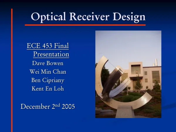
Optical Ethernet Design Receiver Group G1 David Gewertz Ryan Baldwin Geoffrey Sizemore Presented : February 14, 2002
Outline • Understanding of previous team progress • removal, redesign, debug • Maxim Evalution Kit • understand chip functionality and future applications • Redesign transeiver for Gigabit Ethernet • replacement, improvement • Testing and verification • BER, compatibility, signal quality
Previous Team’s Progress • Design Team Objectives • Separation of optical transceiver from Intel card • Redesign and fabrication of new board containing optical functionality • Reintegration of board with Intel setup • Verification to meet optical ethernet specifications • Use of evaluation kits in further design efforts
Maxim Evaluation Kits • MAX3266 Evaluation Board Diagram Photodiode emulation circuit replaced by photodetector
Maxim Evaluation Kits • Circuit Modifications to Minimize Current Loss • Replacing series resistors and adding a 67-Ohm resistor in parallel
MAX3266 Board Functionality • Photodiode emulation • inexpensively mimic the output of a photodetector for chip feature testing • Transimpedance Amplifier (TIA) on chip • converts current to voltage • converts single-ended input to differential output • 1 mA p-p input = 250 mV p-p output • 10 micro-A p-p input = 2.5 mV p-p output
Maxim Evaluation Kits • MAX3264 Evaluation Board Diagram
MAX3264 Board Functionality • Proper termination impedance and series capacitors to maintain voltage regularity • Buffer on chip • maintains integrity of output from TIA • Limiting Amplifier on chip • provides 55 dB gain with 1.2 Volt max • low jitter enables higher speeds • RMS Power Detection
Testing and Verification • BERT • Tektronix GTS 1250 (1250 Mb/s) • desired BER = 10-12 or 1 error every terabit • Example - For a 4 MB MP3, that would be one bit error for every 31,000 songs transferred • Tektronix CSA 7xxx Scope • accurately measures and records Gb eye diagrams • uses specially designed Communications Signal Analyzer software
Design • Single PCB with both chips • Interface with other design groups (OE, TX) • Interference-free implementation of a single power source to drive all active components
Conclusions • Gb Ethernet technology has been researched and understood • Fall 2001 group projects have been studied for increased understanding and legacy development • Maxim data sheets have been analyzed • Initial research has been completed
Conclusions • Next Steps • Get previous team’s testbed up and functional • Connect and test Maxim boards • Understand development of a receiver module and implement it using our own design