Download
1 / 59
590 likes | 715 Views
HIGH CAPACITY PBX SYSTEM - TECHNICAL INTRODUCTION -. PURPOSE. Purpose of this presentation is to summarize the technical points about DS200L system. SYSTEM DEFINITION. DS200L system consists of : ♣ TW200 (Tower200) towers ♣ PCU200 (PC Unit) Block, ♣ DCC Block, ♣ A network switch,

E N D
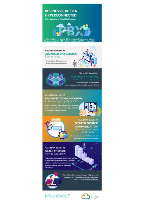
PURPOSE • Purpose of this presentation is to summarize the technical points about DS200L system.
SYSTEM DEFINITION DS200L system consists of : ♣TW200 (Tower200) towers ♣PCU200(PC Unit) Block, ♣ DCC Block, ♣ A network switch, ♣ An inverter ♣PowerBlock ( DELTA etc. ) In the figure, DS200L system and its units in a 6-rack cabinet and19” closet are illustarated.
PROPERTIES Fundamental differences of the DS200L system from the DS200 systems are briefly as follows : • It has high capacity, • It is possible to install UTIL 4E1 cards on UTIL200 cards, • The PCU200 Block fulfills the tasks of the CPU card, • It is possible to utilize the CC200 cards in racks, instead of the CPU200 card • It has the DCC Block, • The units communicate over LAN through TCP/IP connection, • The Delta power block or similar power supplies are utilized instead of the SPS200 power supply at high capacities, • It utilizes Inverter and Network Switch. NOTE: Since the system can support 16 towers, its maximum capacity is calculated as 16*672= 10752.
Physical Connections of the System • Connect the maintenance computer, the LAN Adaptor cards in the TW200 towers, the power block and the PCU200 units to the network switch for maintaining TCP/IP connection. • The DCC, the inverters and the SPS248 units are connected to the power block. • The PCU200 and the network switch, on the other hand, are connected to the inverters and receive the necessary voltage for their operation from the inverters.
TW200 RACK STRUCTURE • A TW200 tower consists of 3 TW200 racks, namely 1 main rack and 2 auxiliary racks (In fact, only a single main rack is enough to establish a tower) . • The rack structure of TW200 is similar to the usual DS200 rack structure. • The UTIL200, CPUKON and other cards that are used in DS200 racks are also used in TW200 racks. • Since the PCU Block functions as the main processor in the DS200L system, no CPU card is available. The CC200 card is employed instead of the CPU card.
NOTE: No redundant CC200 is used in the DS200L exchange. Since the PCU200 block fulfills the tasks of CPU, redundancy of the PCU200 block is available in the DS200Lexchange. CC200 MODULE
CC200 MODULE • The CC200 card is employed in the DS200L system instead of the CPU200 card. • Although its hardware structure is the same as that of the CPU200 card that is used in DS200 systems, their functions are completely different. • The function of the CC200 is : to provide communication between the PCU200 block and the racks. • The CC200, CPUKON and LAN Adaptor cards work likewise in coordination, but the LAN Adaptor software used for DS200L is completely different. • Software is loaded to the EPROMs on the CC200 card with an EPROM programmer. On the other hand, other CC software is loaded through wbcpv commands that are entered in the MSDOS command line.
UTIL 4E1 CARD • Speech channels between the TW200 towers and the DCC block are connected through the E1 channels of the towers. • Via this card, at most 12*31= 372 channels are supplied between towers. At most 372 extensions call talk to eachother towers simultaneously. • The UTIL 4E1 card is installed on the UTIL200 card. • 4 E1 ports are available on it. Each E1 port has 31 speech channels. • Since there are 3 racks in a tower (TW200), at least 1, at most 12 E1 connections can be made per tower. • The E1 ports that are on the UTIL 4E1 cards are connected directly to the DCC 8E1 cards that are in the DCC Block. • There is an EPROM on each of the UTIL200 and UTIL 4E1 cards. Software is loaded to those EPROMs with an EPROM programmer.
INFORMATION • PCU200 ( PC Unit ) is a processor structure that has been based on a 19” PC which controls all functions of the exchange. • The PC that functions as the PCU200 is 19” in width, 2Uin height and 80 cm in depth. It is placed in a 19” closet. ***The master software of the exchange runs under the Linux Suse 10.1 O/S. ►The minimum requirements of a DS200L PCU block: • Pentium IV 2.4 GHz. processor • 60 GB hard disk • 1 GB RAM
PCU200 • The master software runs under LINUX in real time and performs its functions by means of a file system. • Using this file system, the entire exchange parameters, statistical data, call records, alarm information, etc. are stored in separate files on hard disk. PCU200 and the redundant PCU200.
COMMUNICATION • PCU200 communicates with the other units within the exchange over the TCP/IP protocol. • PCU200 is the unit that initiates intra-exchange communication. • Communication among the exchange units are performed entirely by PCU200. • Units that communicates with PCU200 over the IP network, DCC and TW200 units are sorted and queried according to an IP and TCP Port number table that is on PCU200.
COMMUNICATION • Thanks to that structure, both of the blocks that carry out TDM and IP switching can be controlled by the same center. • Besides, PCU200, which provides communication through the Ethernet structure, has completely been isolated from exterior factors. • That fact is extremely essential considering that the system security is thus increased.
REDUNDANCY • It is possible to back up the PCU200 block upon wish, with another PC that is a one-to-one copy of it. • The redundant and functional PCU200 blocks are in connection with each-other through Ethernet. • In case of any malfunction that occurs in the functional PCU200 block, the redundant PCU200 directly becomes functional. • That transition is transparent, i.e., users observe no interruption in system services.
DIRECTORY STRUCTURE OF PCU200 • The PC on which PCU200 runs has no direct user interface. The purpose here is protecting the computer from any kind of user errors. • User computers that are on the same LAN provide access to PCU200. By this way, while it is possible to access all information on PCU200, raw data within the exchange is protected. • As a result of all those protection measures, the exchange security has been maximized.
DIRECTORY STRUCTURE OF PCU200 • A special partition has been created on the hard disk of the PCU200 computer.There is a directory, namely karel, under that partition. Pieces of software and the filesthe exchange creates as it operates are in a subfolder which is under that directoryand which is compatible with the exchange software.For example: karel/ bin/ z_new_23.rpm
DIRECTORY STRUCTURE OF PCU200 • The directory structure above is created by theuser on the Windows PC in order to make copy process from this PC to PCU200. • Since thesame directory structure exists on the Linux PC (PCU200), thatoperation isalso necessary to check and copy the specified files.
DIRECTORY STRUCTURE OF PCU200 ► There are 3 folders under the directory karel, namely sbin, binand home. ●There are 6 files in the folder sbin. 1) dsinit:It specifies the master software that is to run in the system. 2)check:It allows the read-write-execute permissions of the files to be set. 3)dslog: It allows the system logs to be displayed. 4)stop: It allows the system to be stopped. 5)start: It allows the system to be started up. 6)arpsave:IP and MAC addresses of LAN Adaptor cards in TW200 towers are stored in this file.
DIRECTORY STRUCTURE OF PCU200 • There are 5 files in the folder home. • log:Files for analyzing (for maintenance) related to the entire operations, which are created during the operation of the exchange are kept in this folder. *** 2 million lines of log data in total are stored in two files(curr.log&prev.log) ►One of them, the file curr.log, is the file to which active operations of the exchange is recorded. ►On the other hand, the file prev.log contains logdata that has been recorded during the previous session. ►nks_err.log andnks.logare the log files that pertain to the NetConsole Server.
DIRECTORY STRUCTURE OF PCU200 2)cm: The files cm00.bin, cm01.bin, cm15.bin, which contains the callrecord information of the exchange are kept in this folder. ♣Size of each file is16 MB ♣ 7.250.000 call records in total are stored in the exchange memory. NOTE : NetConsole Server is embedded and automatically runs on the MASTER PC.
DIRECTORY STRUCTURE OF PCU200 3)conf: This file consists of two parts. • The folder confand the text files pbxcomm.conf and dsinit.conf, which are to be located in it, are supposed to be created manually before installation of the exchange begins. • pbxcomm.confis the file that specifies the IPaddresses, orders and TCP Portnumbers of TW200 towers and DCC block. • Explanations of pbxcomm.conf are written inside the file. The file dsinit.confspecifies the master software to run on thesystem .
DIRECTORY STRUCTURE OF PCU200 4)Data: The files pertaining to the entire programmed parameters in the exchange are stored in this folder. 5)Alarm: The files alarm00.bin and alarm01.bin, which contain alarm information of the exchange are stored in this folder.
DCC (Digital Cross Connect) BLOCK A DCC block consists of the units below: • DCC Chassis • DCC Backplane • DCC Utility Card • DCC 8E1 Card • DCC Power In Card
DCC • The DCC Block is the switching matrix that fulfills the main switching functionfor the exchange. • Its structure includes the main switching controller card ( DCC UTIL), 14 of 8E1 card slots anda power regulation card (DCC Power In). • Due to its standard 19” structure,it is placed in the same 19” cabinet withPCU.
DCC Chassis • The DCC chassis is a 19”, 6U-high box, which has been formed into aluminum cage structure and whichmechanically places the entire cards in contact. • It has slots for 17 cards inside, which is composed of plastic rails that are at the top and bottom of the slot.
DCC Backplane • Communication of the entire electronic units in the DCC block is over the DCC backplane. • The DCC backplane transfers all signals used by DCC cards to pertinent card slots and it distributes the power coming from the DCC Power In card to all card slots. • There are 2 special slots for the DCC Utility card and one special slot for the DCC Power In card on the backplane, as well as 14 slots for DCC 8E1 cards.
DCC Power In Card • The DCC Power In card regulates the -48 VDC feed voltage it receives from the power block of the DS200L system and transfers it to the backplane. • The Power Control Card controls the -48 VDC voltage fed to the DCC unit and minimizes surges in voltage with fuses and regulators on it. • Each DCC unit has only a single Power In card. The card definitely must not be removed from its slot while the system is on. • The card also generates the reference signal for the backplane, which is 1.5 VDC.
DCC Power In Card & LED Statuses ● The LEDs signifying +3V3 and +1V5 statuses are supposed to becontinuously ON state during the normal operation of the system, whereas all the other LEDs are supposed to be off. ● In case the LED statuses are different from what have been specified here, the system should be checked.
DCC UTIL Card • The DCC UTIL card is the main unit, which controls the entire DCC functions and which includes the switching matrix. • The DCC UTIL card consists of the Utility motherboard and the PPC CPU card, which has been attached to the motherboard with two connectors that are on the motherboard. • The main processor of the DCC Utility card is the Power PC CPU card.
DCC UTIL Card • The DCC Utility software is loaded over ftpand HyperTerminal connection. *** DCC UTIL software update has been explained in detail in the DS200L Maintenance Manual.
DCC UTIL Card LED Statuses The LEDs on the DCC UTIL card and their functions have been explained below: POWER: This LED is supposed to be continuously on. If it flashes, then the DCC block must be turned off and then back on after 15 seconds. DSP-A, DSP-B, DSP-C, DSP-D:These LEDs signify that the DSP unit is operational. They are supposed to be blinking. 10 RX, 10 TX, 100RX, 100TX:These are supposed to be flashing during data transmission or reception over local area network (LAN). CPU: It is supposed to blink. M/S (Master/Slave): This LED is supposed to be continuously on, if the master DCC UTIL card is functional in the DCC Block.
DCC UTIL Card LED Statuses LOCK:DCC This LED is supposed to be blinking, if DCC is using external clock. If it flickers, then that signifies there is a problem with the external clock signal. HOLD:This LED is supposed to be continuously on, if DCCis using its own clock signal. 10 BASE-T, 100 BASE-T: If the upper green LED is on after a LAN cable has been attached, then that signifies the connection has been established. On the other hand, the red LED signifies a problem with the cable or the connection.
DCC 8E1 Card • The DCC 8E1 card has 8 E1 lines, as its name already indicates, and it can be installed in the 14 general-purpose slots within DCC. • The DCC 8E1 card receives the 48 VDC feed voltage from the backplane and generates the 3.3 VDC signal it needs. By this way, the power signals within the DCC block have been isolated from each other, so that defective units are prevented from adversely affecting other units. *** 8E1 cards have been numbered starting with the rightmost slot in the DCC Block. (The rightmost slot is numbered as 0, and the leftmost one is numbered as 13.)
DCC 8E1 Card • The DCC 8E1 card has embedded self-test feature. • The DCC 8E1 card is capable of applying BERT to the E1 channels within DCC. By this way, any problem that might occur in the future is easily detected in advance and necessary precautions are taken before system performance deteriorates. • The DCC 8E1 card software can be updated through IDEA program or through ftp connection. *** Refer to the DS200L Maintenance Manual for the topic explaining in detail how to update the DCC 8E1 card software.
DCC 8E1 Card • The DCC E1 lines constitute the main frame for voice transmission system of the exchange. Those lines can be used both to provide means for speech channels between DCC and TW200 towers. • The E1 lines extending to TW200 towers are connected to the 4E1 cards that are in the towers. On doing that, it is obligatory to connect at least one E1 line to each tower.
DCC 8E1 Card • Each E1 line provides 31 speech channels to a tower. It is sufficient to increase number of E1 connections to towers in order to increase number of speech channels. • In case where several E1 channels are connected to the TW200 4E1 card, distribution of speech channels to those E1 lines is arranged by the system automatically. • E1 channels also provide redundancy for each other, such that in case a line is broken during an ongoing conversation, all active conversations are automatically transferred to vacant channels of other E1 lines; by this way, lossless communication is maintained.
Switching Structure of DCC • Intra-rack and inter-rack switching in the DS200L system is conducted over the UTIL200 card, whereas inter-tower switching and switching between towers are conducted over DCC. • The DCC block has a 4096 x 4096 switching matrix. By this way, 8192 channels in the DS200L exchange can be simultaneously used for conversations. • The switching matrix on the DCC block is distributed to the TW200 towers over E1 lines in DCC. Thanks to the isolated E1 structure, trouble-free connections can be established even with the distant TW200 towers.
Switching Structure of DCC • Due to its structure, DCC is continuously in communication with both the TW200 towers and the PCU block. It communicates with the towers over E1 connection, whereas it communicates with the PCU Block over TCP/IP. • Number of 8E1 cards to be installed depends on the capacity of the exchange to be used. • At most 14 DCC 8E1 cards can be installed in the DCC block. By this way, the capacity may vary between 8 and 112 E1 lines.
Switching Structure of DCC • If the capacity provided by only a single DCC is not enough, then it may be expanded by including a second DCC in the system, so that both the switching capacity is increased from 4096 x 4096 to 8192 x 8192, and number of E1 lines is increased up to 224. • The E1 lines in the DCC are used to establish speech channel connection with the TW200 towers. 1 to 12 E1 lines can be connected to each tower, depending on capacity requirements. (Each E1 has 31 channels.) • By this way, it is possible to provide 31 to 372 speech channels for 672 extensions. Number of the E1 lines to be allocated to towers is one of the most important parameters that determine exchange capacity.
NETWORK SWITCH NOTE: IP addresses of the devices specified above must be so adjusted that they are in the same localarea network.
NETWORK SWITCH • Its function is to provide the exchange with TCP/IP connection and to coordinate the connection. • Communication and information exchange in the DS200L systems are carried out over the IP network. • The network switch is located in the 19” closet.
NETWORK SWITCH ►The Ethernet cables that are supposed to be connected tothe switchare asfollows: ♣The Ethernet cables coming from the LAN Adaptor cards in TW200 towers , ♣The Ethernet cables coming from the PCU200 Block and the redundant PCU200 Block , ♣The Ethernet cable of the computer that is connected to the exchange for maintenance purposes , ♣The Ethernet cable coming from the DCC Block , ♣The Ethernet cable coming from the Power Supply.
STEPS FOR INSTALLING THE SYSTEM ►When installing the DS200L system, after the physical connections havebeen made, the instructions below should be followed in the specifiedorder. The computer that is mentioned as “the maintenance computer”below is a user computer in thesame local area network, on which programmingwork pertainingto the system is done, and which runs theWindows Operatingsystem.
STEPS FOR INSTALLING THE SYSTEM • Power ON the desired towers in the system. Turn ON themaintenance PC. • Define separate IP addresses for each LAN adaptor card ineveryTW200 tower.Details regarding how to define IP addresses have beenexplained in the DS200LMaintenance Manual. NOTE: In DS200L system, CPUKON dipswitch settings should be set properly and stable.For upgrading the CC200 card softwareCOM2 port should be used and set for Serial connection for upgrading required softwares, COM1 port is used for connection to the network should be set to LAN Adaptor output. • Power ON the DCC block. • Define the IP address for the DCC block. That is donethrough the serial portover the HyperTerminal connection. *** Details regarding that operation are in the DS200L Maintenance Manual.