Download

1 / 40
400 likes | 406 Views
MCS-MAGNUM EXV LOGIC Training Presentation www.mcscontrols.com. Rev. I - 12/20/2019. MCS EXV CONTROL PRESENTATION. 1. EXV CONTROLLER & VALVE a. Controller Description b. Wiring c. Specifications. 2. BASIC CONTROLS (INFINITE CAPACITY) a. Set Points b. Control Zones.

E N D
MCS-MAGNUM EXV LOGIC Training Presentation www.mcscontrols.com Rev. I- 12/20/2019
MCS EXV CONTROL PRESENTATION • 1. EXV CONTROLLER & VALVE • a. Controller Description • b. Wiring • c. Specifications • 2. BASIC CONTROLS (INFINITE CAPACITY) • a. Set Points • b. Control Zones • 3. BASIC CONTROLS (STEP CAPACITY) • a. Set Points • b. Relay Outputs for steps • 4. EXV ADAPTIVE CONTROL • a. Rate of Change • b. Load Adjust • c. Low Suction Control
MCS EXV CONTROL PRESENTATION Continued 5. LIQUID LEVEL CONTROL 6. EXV MODES, STATES & LOGIC CHART 7. FINE TUNING YOUR MCS-EXV-DRIVER
EXV CONTROLLER & VALVE - DESCRIPTION - WIRING DIAGRAM - SPECIFICATIONS
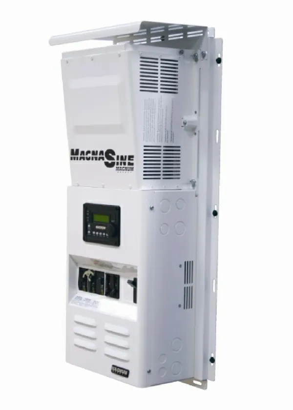
MCS-EXV-DRIVER • Standard 110 to 240 VAC ±10% (50/60 Hz) • Option 24 VAC ± 10% (50/60 Hz) • 2 position led display • Auto / Manual operation • Closes valve on power failure • Eliminates need for Liquid Line Solenoid • 33% faster valve operation • CSA / UL approved
MCS EXV New Feature Firmware Version 6.7 VERSION 6.7 - HARDWARE 3.0 • New Feature was added for MCS-EXV-DRIVER with firmware 6.7 or greater. • OO= Steps to Overdrive when Opening • OC= Steps to Overdrive when closing • Both are separate variables and can be set with a value between 2 to 8% • Old version of firmware was set to overdrive the valve fixed at 10% of total steps. • By using the new feature settings, the valve will not have to be overdriven as much. These new overdrive parameters are just when the MCS-EXV-DRIVER is running and voltage asked for full open or full closed. When the MCS-EXV-DRIVER is powered up, the valve must still be overdriven the total steps + this overdrive amount. Have to assume worst case at power up, the valve is fully open.
MCS-EXV-DRIVER WIRINGSporlan WHITE WIRE TO ANALOG OUTPUT BLACK & SHIELD TO ANALOG OUTPUT GROUND B L A C K GREEN W H I T E B L A C K W H I T E R E D ELECTRIC EXPANSION VALVE BLACK TO LINE 120/240 VAC WHITE TO NETURAL 120/240
MCS-EXV-DRIVER WIRINGAlco WHITE WIRE TO ANALOG OUTPUT BLACK & SHIELD TO ANALOG OUTPUT GROUND W H I T E B R O W N W H I T E B L A C K B L A C K B L U E ELECTRIC EXPANSION VALVE BLACK TO LINE 120/240 VAC WHITE TO NETURAL 120/240
MCS-EXV-DRIVER WIRINGDanfoss WHITE WIRE TO ANALOG OUTPUT W H I T E B L A C K GREEN R E D BLACK & SHIELD TO ANALOG OUTPUT GROUND W H I T E B L A C K ELECTRIC EXPANSION VALVE BLACK TO LINE 120/240 VAC WHITE TO NETURAL 120/240
MCS-EXV-DRIVER WIRINGCarel WHITE WIRE TO ANALOG OUTPUT Y E L L O W BLACK & SHIELD TO ANALOG OUTPUT GROUND W H I T E B L A C K B R O W N W H I T E G R E E N ELECTRIC EXPANSION VALVE BLACK TO LINE 120/240 VAC WHITE TO NETURAL 120/240
MCS EXV BASIC CONTROL (Infinite Capacity Control) - SET POINTS - CONTROL ZONES
MCS-EXV-DRIVER SET POINTS (MCS CHILLER) SH Target ± Ctl Zone SH Fine & Course Adj EXV Min & MAX % Timing Ctl Set Points
MCS-EXV-DRIVER SET POINTS (MCS CHILLER) Individual Zone Ctl Individual ROC Ctl Zone 1 Speed Ctl
EXV ABOVE & BELOW ZONES 18 16 15 14 13 12 11 10 9 8 7 6 5 4 S U P E R H E A T
MCS EXV BASIC CONTROL (Step Capacity Control) - SET POINTS - RELAY OUTPUT SETUP FOR STEPS
MCS-EXV-DRIVER SET POINTS No Change • With EXV Step Control the following Set Points are changed: • SP 11, ‘EXV LOAD ADJUST’ is deleted • SP 14, ‘EXV LOAD DIV’ is added • As the Amp draw % changes this divides the EXV % change calculated as the ratio of slide movement to valve movement • [(Max slide% – min slide%) / (Max vlv% - min vlv%)] +1
MCS-EXV-DRIVER SET POINTS No Change No Change • The remaining set points remain active with the following changes: • SP 17 TIME & MAX TIME ALLOWED are setup
MCS RELAY OUTPUT CFG SETUP (Step Capacity Control) • Cfg RO screen when Type = Step w\ EXV setup following: • EXV Starting % when this compressor is the lead • EXV Load Adjust %, the % increase to apply to the current EXV opening when this compressor is not the lead and is started • EXV Unld adjust %, the % decrease to apply to the current EXV opening when this compressor is not the last compressor and is turned off
MCS RELAY OUTPUT MCS-CONNECT EXV START WHEN LEAD COMPRESSOR STARTING % COMPRESSOR TIME IN STARTUP
EXV ADAPTIVE CONTROL - RATE of CHANGE - LOAD ADJUSTMENT - LOW SUCTION CONTROL
MCS EXV ROC FUNCTION (MCS CHILLER) - TIME field in set point 9 is the number of seconds to look at the slope of the superheat (ROC). - MAX TIME ALLOWED field is the maximum value the TIME field can be set to.
MCS EXV ROC FUNCTION (MCS CHILLER) - VALUE field in set points is the ROC allowed for that zone - TIME field is the minimum time the EXV is kept in the HOLDING state.
MCS EXV ROC FUNCTION (Special Action) • Super Heat Above Control Zone- • If above zones and the EXV ROC is negative and < then SP 70 then hold for number of seconds in time field. • If in Zone 2 and the EXV ROC is negative and < then SP 69 then hold for number of seconds in time field. • If in Zone 1 and the EXV ROC is negative and < then SP 67 then hold for number of seconds in time field. • Super Heat Below Control Zone- • If in Zone 1 and the EXV ROC is positive and > then SP 67 then hold for number of seconds in time field. • If in Zone 2 and the EXV ROC is positive and > then SP 69 then hold for number of seconds in time field. • If in Zone 3 and the EXV ROC is positive and > then SP 70 then hold for number of seconds in time field.
MCS EXV ROC FUNCTION (Special Action) • EXV ROC FAST- • If we are opening or closing at 2x, if the absolute value of the super heat ROC is > than the value in SP 71 we will hold for the time in SP 71. • EXV ROC CHG- • If the super heat state is ‘EXV is HOLDING’ this value specifies the maximum value of the change % that can be made.
MCS EXV LOAD ADJ FUNCTION (MCS CHILLER) - VALUE field, in EXV LOAD ADJ, is the value the EXV will be adjusted each time the compressor capacity is adjusted. Used on modulating compressors.
MCS EXV LOW SUCTION ADJUSTMENT • HOW IT NORMALLY OCCURS • Condenser is sized for high ambient • We have a low ambient condition • Usually when the last stage of condensing is turned on • WHAT NORMALLY HAPPENS • Because of the pressure drop some of the liquid boils off before it gets to the EXV • Now you have liquid and vapor mixed requiring the EXV to open • This occurs within 1 minute and system returns to normal in about 3 minutes.
GRAPH OF LOW SUCTION OCCURING Notice the 3rd stage of condensing comes on 15 seconds later the suction psi crashes
MCS EXV LOW SUCTION ADJUSTMENT (MCS CHILLER) • Once the Magnum has determined it is in a LOW SUCTION situation it will take the EXV COURSE ADJ and multiply it by the value in the TIME field of SP 13. It will continue to make this adjustment, based on the value in Set Point 56 ‘PULSE or CMP LOAD DELAY’ until the situation is cleared.
MCS-EXV FLOODED LEVEL CONTROL No Change • EXV set points 9 & 10 now reflect refrigerant level • EXV other set points remain same
MCS-EXV FLOODED LEVEL CONTROL New Set Points • Set point 9 & 217 specify the range that will be used to maintain and even refrigeration level when required. • Set point 109 specifies the upper limit and will cause a safety shutdown.
EXV UNIT MODES & STATES - EXV DRIVER MODES - EXV STATES - EXV LOGIC CHART
MCS EXV Unit Modes • Auto Mode – The unit defaults to this mode after every power up. In this mode, the MCS-EVX-DRIVER-XX positions the valve according to the analog input control voltage. • Manual Mode – When in auto mode, holding the ‘Auto/Manual’ key for 5 seconds, then entering the authorization number switches the unit into Manual mode. In this mode, the valve position is controlled with the keypad’s directional arrows. • Power Down Mode – If the main power is disconnected, the controller switches to the power down mode. In this mode, the controller uses internal power to close the expansion valve.
FINE TUNING YOUR MCS-EXV-DRIVER Part 1 Verify what has been done. Completed the MCS EXV DRIVER setup specifying valve type. Completed the setup for starting valve position in cfg. If a modulating compressor verify starting % is set. Using MCS-Connect, review start up. Set history sample rate at 1 sec Place RUN/STOP switch to RUN
FINE TUNING YOUR MCS-EXV-DRIVER Part 2 • Normal MCS CONTROLLER start up. • At 2 to 3 minutes from compressor starting, suction superheat should be between ± Control Zone 1. • If above Control Zone 1 increase starting valve opening %. • If below Control Zone 1 decrease starting valve opening %. • At end of startup Discharge temperature should be 110°F or higher. • If less than 105°F and we have a modulating compressor and the load is adequate increase the startup speed. • Otherwise increase the startup time. • Watch changing capacity, if superheat is moving too much as capacity changes, lower LOAD ADJUST set point. • Pull Graph at about 15 minutes after starting, this will allow you to review startup results. • If Unit is stable but EXV is hunting check time in superheat target. The length of time to calculate superheat ROC should be no less then 3 and no higher than 8. If hunting lower by 1 and watch results.
For additional information please visit our website www.mcscontrols.com Or call MCS at 239-694-0089