Download
1 / 4
40 likes | 151 Views
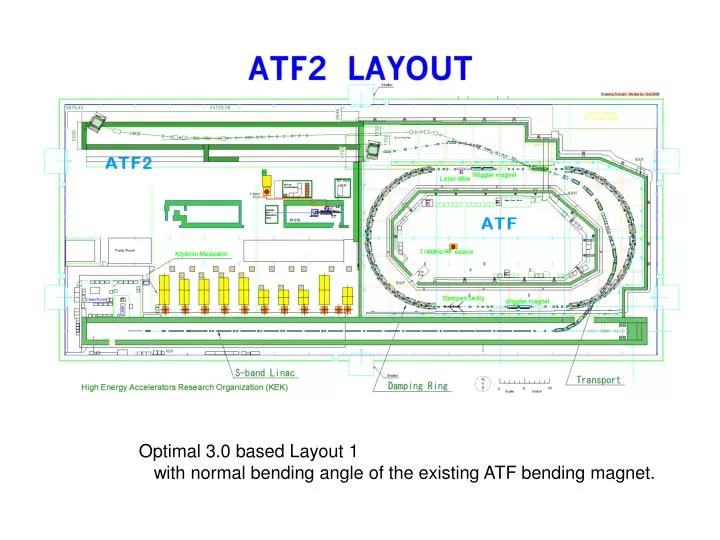
Optimal 3.0 based Layout 1 with normal bending angle of the existing ATF bending magnet. Optimal 3.0 based Layout 2 with the modified bending angle of the existing ATF bending magnet. ( 15mrad weaker than nominal bending angle ). Optimal 3.0-like Extraction Optics.

E N D
Optimal 3.0 based Layout 1 with normal bending angle of the existing ATF bending magnet.
Optimal 3.0 based Layout 2 with the modified bending angle of the existing ATF bending magnet. ( 15mrad weaker than nominal bending angle )
Optimal 3.0-like Extraction Optics Dispersion Matching and Phase advance between kickers were fixed. but … The distance between bends should be extended by 3 m. The K-value of QP9X is too strong (~2.5 ).
From Mover Requirement, Ds (Q&Q) > 0.60m, Ds (Q&B) > 0.75m From QBPM Requirement, Ds (Q&Q) > 0.50m, Ds (B&Q) > 0.83m, Ds (B&Q) > 0.77m Ds (SF1&QF1) > 0.60m, Ds (QF1&SD0) > 0.60m, Ds (SD0&QD0) > 0.65m QD10 0.900 QD10A 1.300 QF9 0.450 SF6 0.450 QF9A 2.000 QD8 1.700 QF7 0.850 B5 0.850 QD6 2.000 QF5 0.450 SF5 0.450 QF5A 1.300 QD4 0.450 SD4 0.450 QD4A 1.950 B2 0.850 QD2B 0.850 B1 0.850 QF3 1.700 QD2A 4.875 SF1 0.450 QF1 0.550 SD0 0.450 QD0