Download
1 / 104
1.04k likes | 1.07k Views
OPTIC AL MINERALOGY. Geology 265 – Mineralo ji Meral Dogan Lecture : optik mineraloji Dr. Dogan’s homepage. Optik mikroskop -petrografik mikroskop-polarizan mikroskop. Petrographic microscope.

E N D
OPTICAL MINERALOGY Geology 265– Mineraloji Meral Dogan Lecture : optik mineraloji Dr. Dogan’s homepage
Two complimentary theories have been proposed to explain how light behaves and the form by which it travels • Particle theory - release of a small amount of energy as a photon when an atom is excited. • Wave theory - radiant energy travels as a wave from one point to another. • Waves have electrical and magnetic properties => electromagnetic variations. • Wave theory effectively describes the phenomena of polarization, reflection, refraction and interference, which form the basis for optical mineralogy
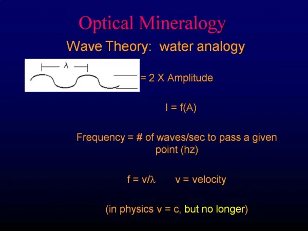
ELECTROMAGNETIC RADIATION The electromagnetic radiation theory of light implies that light consists of electric and magnetic components which vibrate at right angles to the direction of propagation. In optical mineralogy only the electric component, referred to as the electric vector, is considered and is referred to as the vibration direction of the light ray. The vibration direction of the electric vector is perpendicular to the direction in which the light is propagating. The behaviour of light within minerals results from the interaction of the electric vector of the light ray with the electric character of the mineral, which is a reflection of the atoms and the chemical bonds within that minerals. Light waves are described in terms of velocity, frequency and wavelength.
REFLECTION AND REFRACTION At the interface between the two materials, e.g. air and water, light may be reflected at the interface or refracted (bent) into the new medium. For Reflection the angle of incidence = angle of reflection .
For Refraction the light is bent when passing from one material to another, at an angle other than perpendicular. A measure of how effective a material is in bending light is called the Index of Refraction (n), where:
POLARIZATION OF LIGHT . Light emanating from some source, sun, or a light bulb, vibrates in all directions at right angles to the direction of propagation and is unpolarized. In optical mineralogy we need to produce light which vibrates in a single direction and we need to know the vibration direction of the light ray. These two requirements can be easily met but polarizing the light coming from the light source, by means of a polarizing filter.
completely polarized light Unpolarized light strikes a smooth surface, such as a pane of glass, tabletop, and the reflected light is polarized such that its vibration direction is parallel to the reflecting surface. The reflected light is completely polarized only when the angle between the reflected and the refracted ray = 90°.
Index of Refraction in Vacuum = 1 and for all other materials n > 1.0. Most minerals have n values in the range 1.4 to 2.0. A high Refractive Index indicates a low velocity for light travelling through that particular medium.
Snell's law can be used to calculate how much the light will bend on travelling into the new medium. If the interface between the two materials represents the boundary between air (n ~ 1) and water (n = 1.33) and if angle of incidence = 45°, using Snell's Law the angle of refraction = 32°. The equation holds whether light travels from air to water, or water to air. In general, the light is refracted towards the normal to the boundary on entering the material with a higher refractive index and is refracted away from the normal on entering the material with lower refractive index. In labs, you will be examining refraction and actually determine the refractive index of various materials.
Three types of polarization are possible. • 1-Plane Polarization • 2-Circular Polarization • 3-Elliptical Polarization
In the petrographic microscope • In the petrographic microscope plane polarized light is used. For plane polarized light the electric vector of the light ray is allowed to vibrate in a single plane,producing a simple sine wave with a vibration direction lying in the plane of polarization - this is termed plane light or plane polarized light. • Plane polarized light may be produced by • reflection, • selective absorption, • double refraction • scattering.
Double Refraction This method of producing plane polarized light was employed prior to selective absorption in microscopes. The most common method used was the Nicole Prism. .
This method is used to produce plane polarized light in microscopes, using polarized filters. Some anisotropic material s have the ability to strongly absorb light vibrating in one direction and transmitting light vibrating at right angles more easily. The ability to selectively transmit and absorb light is termed pleochroism, seen in minerals such as tourmaline, biotite, hornblende, (most amphiboles), somepyroxenes. Upon entering an anisotropic material, unpolarized light is split into two plane polarized rays whose vibratioin directions are perpendicular to each other, with each ray having about half the total light energy. If anisotropic material is thick enough and strongly pleochroic, one ray is completely absorbed, the other ray passes through the material to emerge and retain its polarization.
PHASE AND INTERFERENCE • Before going on to examine how light inteacts with minerals we must define one term: • RETARDATION - ∆(delta) represents the distance that one ray lags behind another. • Retardation is measured in nanometres, 1nm = 10-7cm, or the number of wavelengths by which a wave lags behind another light wave.The relationship between rays travelling along the same path and the interference between the rays is illustrated in the following three figures.
If retardation is a whole number (i.e., 0, 1, 2, 3, etc.) of wavelengths.The two waves, A and B, are IN PHASE, and they constructively interfere with each other. The resultant wave (R) is the sum of wave A and B.
When retardation is = ½, 1½, 2½ . . . wavelengths.The two waves are OUT OF PHASE they destructively interfere, cancelling each other out, producing the resultant wave (R), which has no amplitude or wavelength .
If the retardation is an intermediate value, the the two waves will: be partially in phase, with the interference being partially constructive and be partially out of phase, partially destructive
If a mineral is placed at 45° to the vibration directions of the polarizers the mineral yields its brightest illumination and percent transmission (T).
Dark areas where retardation is a whole number of wavelengths. light areas where the two rays are out of phase,
RETARDATION • Monochromatic ray, of plane polarized light, upon entering an anisotropic mineral is split into two rays, the FAST and SLOW rays, which vibrate at right angles to each other.
The birefringence for a mineral in a thin section can also be determined using the equation for retardation, which relates thickness and birefringence. • Retardation can be determined by examining the interference colour for the mineral and recording the wavelength of the retardation corresponding to that colour by reading it directly off the bottom of Plate I. • The thickness of the thin section is ~ 30 µm. With this the birefringence for the mineral can be determined, using the equation:
Due to differences in velocity the slow ray lags behind the fast ray, and the distance represented by this lagging after both rays have exited the crystal is the retardation -∆. • The magnitude of the retardation is dependant on the thickness (d) of the mineral and the differences in the velocity of the slow (Vs) and fast (Vf) rays. • The time it takes the slow ray to pass through the mineral is given by the formula above (∆=d(nslow-nfast) • during this same interval of time the fast ray has already passed through the mineral and has travelled an additional distance = retardation.
Minerals can be subdivided, based on the interaction of the light ray travelling through the mineral and the nature of the chemical bonds holding the mineral together, into two classes: 1-Isotropic minerals (izometric minerals) 2-Anisotropic minerals (rest of the crystal system minerals)
In isotropic materials the Wave Normal and Light Ray are parallel. In anisotropic minerals the Wave Normal and Light Ray are not parallel. Light waves travelling along the same path in the same plane will interfere with each other.
Reliyef (optik engebe), becke çizgisi, kırılma indisi (RI) determinasyonu 1-Isotropic Minerals Isotropic materials show the same velocity of light in all directions because the chemical bonds holding the minerals together are the same in all directions, so light travels at the same velocity in all directions. Examples: isometric minerals (cubic):Fluorite, Garnet, Halite Determine the refraction index: Use becke line, relief a-compare the mineral with n of Canadian balsam, or b-compare the known mineral next to it), or c-use oil with known refraction indexto compare
Optical microskope 1-Opaque (opak) minerals 2-Isotropic (izotropik) minerals 3-Anisotropic (anizotropik) minerals If amourphous-mineraloid, coal example
Anisotropic minerals differ from isotropic minerals because: the velocity of light varies depending on direction through the mineral; they show double refraction. When light enters an anisotropic mineral it is split into two rays of different velocity which vibrate at right angles to each other. In anisotropic minerals there are one or two directions, through the mineral,along which light behaves as though the mineral were isotropic. This direction (tetragonal and orthorombic systems) or these directions (hexagonal, monoclinic and triclinic systems) are referred to as the optic axis (or optic axes).
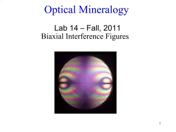
Optix axis (axes) • Hexagonal and tetragonal minerals have one optic axis and are optically UNIAXIAL. • Orthorhombic, monoclinic and triclinic minerals have two optic axes and are optically BIAXIAL. • In Lab, you will examine double refraction in anisotropic minerals, using calcite rhombs.
Anisotropic Minerals • Anisotropic minerals have a different velocity for light, depending on the directionthe light is travelling through the mineral. • The chemical bonds holding the mineral together will differ depending on the direction the light ray travels through the mineral. Anisotropic minerals belong to tetragonal, hexagonal, orthorhombic, monoclinic and triclinic systems. A-Tek optik eksenli minerallerin optik özelliği (Uniaxal optics): • Uniaxial indicatrics, interference figures, optic sign determination Tek optik eksenli mineraller: tetragonal, hexagonal qtz, apatit, nefelin, kalsit, zirkon B-Çift optik eksenli minerallerin optik özellikleri (Biaxial optics): • Biaxial indicatrics, interference figures, optic sign determination Çift optik eksenli mineraller: orthorhombic, monoclinic and triclinic olivin, piroksen, amfiboller, mikalar, plajiyoklas, alkali feldspatlar
ATOMIC PACKING As was discussed in the previous section we can use the electromagnetic theory for light to explain how a light ray is split into two rays (FAST and SLOW) which vibrate at right angles to each other. Also see the figure from the black board (calcite Crystal)
With a random wavefront the strength of the electric field, generated by the mineral, must have a minimum in one direction and a maximum at right angles (90 degrees) to that. Result is that the electronic field strengths within the plane of the wavefront define a n ellipse whose axes are; at 90° to each other, represent maximum and minimum field strengths, and correspond to the vibration directions of the two resulting rays. The two rays encounter different electric configurations therefore their velocities and indices of refraction must be different.
CONTİNUE • There will always be one or two planes through any anisotropic material which show uniform electron configurations, resulting in the electric field strengths plotting as a circle rather than an ellipse. • Lines at right angles to this plane or planes are the optic axis (axes) representing the direction through the mineral along which light propagates without being split, i.e., the anisotropic mineral behaves as if it were an isotropic mineral.
Ordinary and extraordinary ray • Light travelling through the calcite rhomb is split into two rays which vibrate at right angles to each other. The two rays and the corresponding images produced by the two rays are apparent in the above image. The two rays are: • Ordinary Ray, labelled omega w, nw = 1.658 • Extraordinary Ray, labelled epsilon e, ne = 1.486.
Vibration Directions of the Two Rays • The vibration directions for the ordinary and extraordinary rays, the two rays which exit the calcite rhomb, can be determined using a piece of polarized film. The polarized film has a single vibration direction and as such only allows light, which has the same vibration direction as the filter, to pass through the filter to be detected by your eye.
Light ray • With the polaroid filter in this orientation only one row of dots is visible within the area of the calcite rhomb covered by the filter. This row of dots corresponds to the light ray which has a vibration direction parallel to the filter's preferred or permitted vibration direction and as such it passes through the filter. The other light ray represented by the other row of dots, clearly visible on the left, in the calcite rhomb is completely absorbed by the filter.
Slow and fast ray • With the polaroid filter in this orientation again only one row of dots is visible, within the area of the calcite coverd by the filter. This is the other row of dots thatn that observed in the previous image. The light corresponding to this row has a vibration direction parallel to the filter's preferred vibration direction. • It is possible to measure the index of refraction for the two rays using the immersion oils, and one index will be higher than the other. • The ray with the lower index is called the fast ray • recall that n = Vvac/VmediumIf nFast Ray = 1.486, then VFast Ray = 2.02X10¹⁰ m/sec • The ray with the higher index is the slow ray • If nSlow Ray = 1.658, then VSlow Ray = 1.8 1x10¹⁰ m/sec
Remember the difference between: • vibration direction - side to side oscillation of the electric vector of the plane lightand propagation direction - the direction light is travelling. • Electromagnetic theory can be used to explain why light velocity varies with the direction it travels through an anisotropic mineral. • Strength of chemical bonds and atom density are different in different directions for anisotropic minerals. • A light ray will "see" a different electronic arrangement depending on the direction it takes through the mineral. • The electron clouds around each atom vibrate with different resonant frequencies in different directions.
Velocity of light • Velocity of light travelling though an anisotropic mineral is dependant on the interaction between the vibration direction of the electric vector of the light and the resonant frequency of the electron clouds. Resulting in the variation in velocity with direction. • Can also use electromagnetic theory to explain why light entering an anisotropic mineral is split into two rays (fast and slow rays) which vibrate at right angles to each other.
INTERFERENCE PHENOMENA • The colours for an anisotropic mineral observed in thin section, between crossed polars are called interference colours and are produced as a consequence of splitting the light into two rays on passing through the mineral. • In the labs we will examine interference phenomena first using monochromatic light and then apply the concepts to polychromatic or white light.
The relationship (ns - nf) is called birefringence (defined by double refraction), given Greek symbol lower case d (delta), represents the difference in the indices of refraction for the slow and fast rays. • In anisotropic minerals one path, along the optic axis, exhibits zero birefringence, others show maximum birefringence, but most show an intermediate value. • The maximum birefringence is characteristic for each mineral. • Birefringence may also vary depending on the wavelength of the incident light.
Wedge • If our sample is wedged shaped, as shown above, instead of flat, the thickness of the sample and the corresponding retardation will vary along the length of the wedge. • Examination of the wedge under crossed polars, gives an image as shown below, and reveals:
POLYCHROMATIC LIGHT • Polychromatic or White Light consists of light of a variety of wavelengths, with the corresponding retardation the same for all wavelengths. • Due to different wavelengths, some reach the upper polar in phase and are cancelled, others are out of phase and are transmitted through the upper polar. • The combination of wavelengths which pass the upper polar produces the interference colours, which are dependant on the retardation between the fast and slow rays. • Examining the quartz wedge between crossed polars in polychromatic light produces a range of colours. This colour chart is referred to as the