Download
1 / 48
500 likes | 641 Views
CHAPTER 28) DIRECT CURRENT CIRCUITS 28.1) ELECTRMOTIVE FORCE A constant current can be maintained in a closed circuit through the use of a source of emf – which is a device (such as a battery of generator) that produces an electric field and thus may cause charges to move around a circuit.

E N D
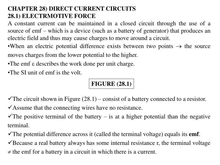
CHAPTER 28) DIRECT CURRENT CIRCUITS • 28.1) ELECTRMOTIVE FORCE • A constant current can be maintained in a closed circuit through the use of a source of emf – which is a device (such as a battery of generator) that produces an electric field and thus may cause charges to move around a circuit. • When an electric potential difference exists between two points the source moves charges from the lower potential to the higher. • The emf describes the work done per unit charge. • The SI unit of emf is the volt. • The circuit shown in Figure (28.1) – consist of a battery connected to a resistor. • Assume that the connecting wires have no resistance. • The positive terminal of the battery – is at a higher potential than the negative terminal. • The potential difference across it (called the terminal voltage) equals its emf. • Because a real battery always has some internal resistance r, the terminal voltage the emf for a battery in a circuit in which there is a current. FIGURE (28.1)
To understand why this is so • The circuit diagram in Figure (28.2a), where the battery of Figure (28.1) is represented by the dashed rectangel containing an emf in series with an internal resistance r. • Imagine moving through the battery clockwise from a to b and measuring the electric potential at various location. • As we pass from the negative terminal to the positive terminal, the potential increase by an amount • As we move through the resistance r, the potential decreases by an amount Ir, where I = the current in the circuit. • The terminal voltage of the battery V = Vb – Va is : FIGURE(28.2) = equivalent to the open-circuit voltage – that is, the terminal voltage when the current is zero. (28.1)
(28.2) • Figure (28.2b) – a graphical representation of the changes in electric potential as the circuit is traversed in the clockwise direction. • The terminal voltage V must equal the potential difference across the external resistance R (the load resistance). • The load resistor - simple resistive circuit element (Figure (28.1)) • - the resistance of some electrical device (such as a toaster, an electric heater, or a lightbulb) connected to the battery (or the wall outlet). • The resistor – a load on the battery because the battery must supply energy to operate the device. • The potential difference across the load resistance : V = IR • Combining this expression with Equation (28.1) :
(28.3) (28.4) • Solving for the current : • If we multiply Equation (28.2) by the current I, • This wquation indicates – that (because P = IV) the total powe output I of the battery is delivered to the external load resistance in the amount I2R and to the internal resistance in amount I2r. • Example (28.1) : Terminal Voltage of a Battery • A battery has an emf of 12.0V and an internal resistance of 0.05. Its terminals are connected to a load resistance of 3.00 . (a) Find the current in the circuit and the terminal voltage of the battery.
Solution Using first Equation (28.3) and then Equation (28.1), we obtain : To check this result, we calculate the voltage across the load resistance R : (b) Calculate the power delivered to the load resistor, the poser delivered to the internal resistance of the battery, and the power delivered by the battery. Solution The power delivered to the load resistor is
Solution (continue) The power delivered to the internal resistance is : Hence, the power delivered by the battery is the sum of these quantities, or 47.1W. Check this result, using the expression P = I . Example (28.2) : Matching the load Show that the maximum power delivered to the load resistance R in Figure (28.2a) occurs when the load resistance matches the internal resistance – that is when R = r. Solution The power delivered to the load resistance is equal to I2R, where I is given by Equation (28.3) :
P Pmax R r 2r 3r When P is plotted versus R as in Figure (28.3), we find that P reaches a maximum value of 2 / 4r at R = r. We can also prove this bydifferentiating P with respect to R, setting the result equal to zero, and solving for R. FIGURE (28.3)
28.2) RESISTORS IN SERIES AND IN PARALLEL • Series • When two of more resistors are connected together as are the lightbulbs in Figure (28.4)a – they are said to be in series. • Figure (28.4b) is the circuit deagram for the lightbulbs, which are shown as resistors, and the battery. • In series connection, all the charges moving through one resistor must also pass through the second resistor. • Otherwise, charge would accumulate between the resistors. • Thus : For a series combination of resistors, the currents in the two resistors are the same because any charge that passes through R1 must also pass through R2. • The potential difference applied across the series combination of resistors will divide between the resistors. FIGURE (28.4a) FIGURE (28.4b)
(28.5) (28.6) • From Figure (28.4b) –because the voltage drop from a to b equals IR1, and the voltage drop from b to c equals IR2 the voltage drop from a to c is : • We can replace the two resistor in series with a single resistor having an equivalent resistance, Req (Figure (28.4c), where : • The equivalent resistance of three or more resistors connected in series is : • The equivalent resistance of a series connection of resistors is always greater than any individual resistance. • series combination of resistor • The circuit current is unchanged
Parallel • Two resistors connected in parallel (Figure (28.5)) • When the current I reaches point a (Figure (28.5b), called a junction, it splits into two parts – with I1 going through R1, and I2 going through R2. • A junction is any point in a circuit where a current can split. • The split results in less current in each individual resistor than the current leaving the battery. • The current I that enters point a must equal the total current leaving that point : • From Figure (28.5) – both resistors are connected directly across the terminals of the battery. • Thus : When resistors are connected in parallel, the potential differences across them are the same. FIGURE (28.5a) FIGURE (28.5b) FIGURE (28.5c)
(28.7) (28.8) • Because the potential differences across the resistors are the same, the expression V = IR gives : • From this result, we see that the equivalent resistance of two resistors in parallel is given by : • or • For three or more resistors in parallel : • parallel combination of resistors • Voltage unchaged
6.0 8.0 4.0 I1 b (a) c a I2 I 3.0 12 2.0 (b) a c b 14 (c) c a • The equivalent resistance of two or more resistors connected in parallel is always less than the least resistance in the group. • Example (28.3) : Find the Equivalent Resistance FIGURE (28.6) • Four resistors are connected as shown in Figure (28.6a). • Find the equivalent resistance between point a and c • What is the current in each resistor if a potential difference of 42V is maintained between a and c?
Solution for (a) • The combination of resistors can be reduced in steps (in Figure (28.6)) • The 8.0 and 4.0 resistors are in series; thus, the equivalent resistance between a and b is 12 (Equation (28.5)). • The 6.0 and 3.0 resistors are in parallel, so from equation (28.7) we find that the equivalent resistance from b to c is 2.0 . • Hence, the equivalent resistance from a to c is 14 . • Solution for (b) • The currents in the 8.0 and 4.0 resistors are the same because they are in series. • In addition, this is the same as the current that would exist in the 14 equivalent resistor subject to the 42V potential difference. • Therefore, using equation (27.8) (R = V/I) and the results from part (a), we obtain :
This is the current in the 8.0 and 4.0 resistors. • When this 3.0A current enters the junction at b, however, it splits, with part passing through the 6.0 resistor (I1) and part through the 3.0 resistor (I2). • Because the potential difference is Vbc across each of these resistors (since they are in parallel). We see that : or I2 = 2I1 . • Using this result and the fact that I1 + I2 = 3.0 A, we find that I1 = 1.0 A and I2 = 2.0 A). • To check : • Therefore
I a I1 I2 I3 9.0 18V 3.0 6.0 b • Example (28.4) : Three Resistors in Parallel • Three resistors are connected in parallel as shown in Figure (28.7). A potential difference of 18V is maintained between points a and b. • Find the current in each resistor. • Calculate the power delivered to each resistor and the total power delivered to the combination of resistors. • Calculate the equivalent resistance of the circuit. FIGURE (28.7)
Solution for (a) • The resistors are in parallel, and so the potential difference across each must be 18V. • Applying the relationship V = IR • to each resistor gives : • Solution for (b) • We apply the relationship P = (V)2 / R to each resistor and obtain : • This shows that the smallest resistor recieves the most power. • Summing the three quantities gives a total power of 200 W.
c 5 1 1 1 1 1 5 a a b b a b c,d a b c,d 1 1 1 1 (d) (c) (b) d (a) • Solution for (c) • We can useEquation (28.8) to find Req : • Example (28.5) : Finding Req by Symmetry Arguments • Consider five resistors connected as shown in Figure (28.8a). Find the equivalent resistance between points a and b. FIGURE (28.8)
Solution • A current entering junction a, and • Then apply symmetry arguments in the circuit (all 1 resistors in the outside loop) – the currents in branches ac and ad must be equal; • Hence, the electric potentials at points c and d must be equal. • This means that Vcd = 0 and, as a result, points c and d may be connected together without affecting the circuit (Figure (28.8b)). • Thus, the 5 resistor may be removed from the circuit and the remaining circuit then reduced as in Figures (28.8c) and d. • From this reduction we see that the equivalent resistance of the combination is 1. • Note that the result is 1 regardless of the value of the resistor connected between c and d.
(28.9) (28.10) • 28.3) KIRCHHOFF’S RULES • Analyze simple circuits using i) V = IR, and ii) the rules for series and parallel combinations of resistors • Complex circuits – simplified to a single loop. • Kirchhoff’s rules : • The sum of the currents entering any junction in a circuit must equal the sum of the currents leaving that junction : • The sum of the potential difference across all elements around any closed circuit loop must be zero :
Rules 1 • First rules is a statemaent of conservation of electric charges. • If we apply the first rule to the junction shown in Figure (28.11a), we obtain : • Figure (28.11b) represents a mechanical analog of this situation, in which water flows through a branced pipe having no leaks. • The flow rate into the pipe equals the total flow rate out of the two branches on the right. • Rules 2 • Second rule follows from the law of conservation of energy. • Let us imagine moving a charge around the loop. • When the charge returns to the starting point, the charge-circuit system must have the same energy as when the charge started from it. FIGURE (28.11a) FIGURE (28.11b)
The sum of the increases in energy in some circuit elements must equal the sum of the decreases in energy in other elements. • The potential energy decreases whenever the charge moves through a potential drop -IR across a resistor or whenever it moves in the reverse direction through a source of emf. • The potential energy increases whenever the cahrge passes through a battery from the negative terminal to the positive terminal. • Kirchhoff’s 2nd rule applies only for circuits in which an electric potential is defined at each points. • To justify that Kirchhoff’s 2nd rule is a statement of conservation of energy, imagine we carry a charge around a loop travelling around the loop and consider charges in electric potential. • The sign conventions when using the second rule : • Figure (28.12a) – because charges move from the high-potential end of a resistor to the low-potential end, if a resistor is traversed in the direction of the current, the change in potential V across the resistor is -IR FIGURE (28.12)
Figure (28.12b) – If a resistor is traversed in the direction opposite the current, the change in potential V across the resistor is +IR • Figure (28.012c) – If a source of emf (assume to have zero internal resistance) is traversed in the direction of the emf (from –ve to +ve), the change in potential V is +. - The emf of the battery increases the electric potential as we move through it in this direction. • Figure (28.12d) – If a source of emf (assumed to have zero internal resistance) is traversed in the direction opposite the emf (from +ve to –ve), the change in potential V is -. - In this case the emf of the battery reduces the electric potential as we move through it. • In order to solve a particular circuit problem, the number of independent equations you need to obtain from the two rules equals the number of unknown currents.
Draw a circuit diagram Label all the known and unknown quantities Apply the junction rule Apply the loop rule (clockwise or counterclockwise) Solve the equations simultaneously for the unknown quantities Problem-Solving Using Kirchhoff’s Rules
I 1 = 6.0V a b - + R1 = 8.0 R2 = 10 - + d c 2 = 12V • Example (28.7) : A Single-Loop Circuit • A single-loop circuit contains two resistors and two batteries, as shown in Figure (28.13). (Neglet the internal resistances of the batteries).\ • Find the current in the circuit. • What power is delivered to each resistor? What power is delivered by the 12V battery? FIGURE (28.13)
Solution for (a) • There are no junctions in this single-loop circuit, thus, the current is the same in all elements. • Assume that the current is clockwise (Figure 28.13) • Traversing the circuit in the clockwise direction, starting at a, we see that ab represents a potential change of +1, bc represents a potential change of –IR1, cd represents a potential change of - 2, and da represents a potential change of –IR2. • Applying Kirchhoff’s loop rule gives : • V = 0 • 1 – IR1 - 2 –IR2 = 0 • Solving for I and using the values given in Figure (28.13), we obtain :
Solution for (a) (continue) • The negative sign for I indicates that the direction of the current is opposite the assumed direction. • Solution for (b) • Hence, the total power delivered to the resistors is P1 + P2 = 2.0W. • The 12V battery delivers power I2 = 4.0W. • Half of this power is delivered to the two resistors, as we just calculated. • The other half is delivered to the 6V battery, which is being charged by the 12V battery. • If we had included the internal resistances of the batteries in our analysis, some of the power would appear as internal energy in the batteries; as result, we would have found that less power was being delivered to the 6V battery.
Example (28.8) : Applying Kirchhoff’s Rules Find the currents I1, I2, and I3 in the circuit shown in Figure (28.14). 14V • Solution • Choose the directions of the currents as labeled in Figure (28.14). • Applying Kirchhoff’s junction rule to junction c gives : I1 + I2 = I3 ------ (1) • We now have one equation with three unknowns – I1, I2, and I3. • There are three loops in the circuit – abcda, befcb, and aefda. • Need only two loop equations to determine the unknown currents. e f + - 4 I2 I1 - + b c 6 I3 10V a d 2 FIGURE (28.14)
Apply Kirchhoff’s loop rule to loops abcda, and befcb and tranversing these loops clockwise, we obtain the expressions. • abcda : ------- (2) • befcb : ------- (3) • Loop befcb – we obtain a positive value when traversing the 6 resistor because our direction of travel is opposite the assumed direction of I1. • Expressions (1), (2), and (3) represent three independent equations with three unknowns. • Substituting Equation (1) into Equation (2) gives : • -------- (4) • Dividing each term in Equation (3) by 2 and rearranging gives : • -------- (5) • Substracting Equation (5) from Equation (4) eliminates I2, giving :
Solution (continue) • Using this value of I1 in Equation (5) gives a value for I2 : • Finally, I3 = I1 + I2 = -1A • The fact that I2 and I3 are both negative indicates only that the currents are opposite the direction we choose for them. • However, the numerical values are correct.
4.00V d e - + I3 I3 5.00 3.00 f c I2 I1 5.00 I1 g b + - 8.00V I=0 + - a h - + 3.00V 6.00F • Example (28.9) : A Multiloop Circuit • Under steady-state conditions, find the unknown currents I1, I2, and I3 in the multiloop circuit shown in Figure (28.15). • What is the charge on the capacitor? • Solution • Because the capacitor represents an open circuit, there is no current between g and b along path ghav under steady-state conditions. • Therefore, when the charges associated with I1 reach point g, they all go through the 8.00V battery to point b; hence, Igb = I1. • Labeling the currents as shown in Figure (28.15) and applying Equation (28.9) to junction c, we obtain • I1 + I2 = I3 (1) FIGURE (28.15)
Solution (continue) • Equation (28.10) applied to loops defcd and cfgbc, traversed clockwise, gives : • defcd (2) • cfgbc (3) • From Equation (1) we see that I1 = I3 – I2, which, when substituted into Equation (3), gives: • (4) • Substrating Equation (4) from Equation (2), we eliminate I3 and find that : • Because our value for I2 is negative, we conclude that the direction of I2 is from c to f through the 3.00 resistor. • Despite this interpretation of the direction, however, we must continue to use this negative value for I2 in subsequent calculations because our equations were established with our original choice of direction.
Solution (continue) • Using I2 = -0.364A in Equation (3) and (1) gives : I1 = 1.38 A, and I3 = 1.02 A • Solution for (b) • Apply Kirchhoff’s loop rule to loop bghab (or any other loop that contains the capacitor) to find the potential difference Vcap across the capacitor. • We enter this potential difference in the equation without reference to a sign convention because the charge on the capacitor depands only on the magnitude of the potential difference. • Moving clockwise around this loop, we obtain : • Because Q = C Vcap (see Equation (26.1)), the charge on the capacitor is :
28.4) RC CIRCUITS • Steady-state circuits – the current is constant • Circuits containing capacitors – the current vary in time • A circuit containing a series combination of a resistor and a capacitor = RC Circuit. • Charging a Capacitor • The capacitor in Figure (28.16) is initially uncharged. • No current while switch S is open (Figure (28.16b). • Then the switch is closed at t=0 - charge begins to flow, setting up a current in the circuit, and the capacitor begins to charge. • During charging, charges does not jump across the capacitor plates because the gap between the plates represents an open circuit. • Instead, charge is transferred between each plate and its connecting wire due to the electric field established in the wires by the battery, until th capacitor is fully charged. FIGURE (28.16)
(28.11) • As the plates become charged, the potential difference across the capacitor increases. • The value of the maximum charge depends on the voltage of the battery. • Once the maximum charge is reached, the current in the circuit is zero because the potential difference across the capacitor matches that supplied by the battery. • To analyze this circuit quantitatively, let us apply Kirchhoff’s loop rule to the circuit after the switch is closed. • Traversing the loop clockwise gives : • where q/C is the potential difference across the capacitor and IR is the potential difference across the resistor. • For the capacitor, notice that we are traveling in the direction from the positive plate to the negative plate; this represents a decrease in potential.
(28.12) (Current at t=0) = (Maximum Current) • Thus, we use a negative sign for this voltage in Equation (28.11). • q and I are instantaneous values that depend on time as the capacitor is being charged. • Equation (28.11) – to find the initial current in the circuit and the maximum charge on the capacitor. • At the instant the switch is closed (t=0), the charge on the capacitor is zero. • And from Equation (28.11), we find that the initial current in the circuit Io is a maximum and is equal to : • At this time, the potential difference from the battery terminals appears entirely across the resistor. • When the capacitor is charged to its maximum value Q, charges cease to flow, the current in the circuit is zero, and the potential difference from the battery terminals appears entirely across the capacitor.
(Maximum charge on the capacitor) (28.13) • Subsituting I = 0 into Equation (28.11) gives the charge on the capacitor at this time: • To determine analytical expressions for the time dependence of the charge and current – solve Equation (28.11), i.e. a singel equation containing two variables, q and I. • The current in all parts of the series circuit must be the same. • Thus, the current in the resistance R must be the same as the current flowing out of an into the capacitor plates. • This current is equal to the time rate of change of the charge on the capacitor plates. • Thus, we substitute I = dq/dt into Equation (28.11) and rearrange the equation :
To find an expression for q, we first combine the terms on the right-hand side : • Now we multiply by (dt) and devide by (q - C) to obtain : • Integrating this expression, using the fact that q = 0 at t = 0, we obtain : • From the definition of the natural logarithm, we can write this expression as : (28.14) Charge versus time for a capacitor being charged
Where e is the base of the natural logarithm and we have made the substituiton C=Q from Equation (28.13). • We can find an ecpression for the charging current by differentiating Equation (28.14) with respect to time. • Using I = dq/dt, we find that : • Figure (28.17) - Plot of capacitor charge and circuit current versus time. • The charge is zero at t=0. • Approaches the maximum value C at t . • The current has its maximum value Io = /R at t=0 and decays exponentially to zero as t . • The quantitiy RC, which appears in the exponents of Equation (28.14) and (28.15) = the time constant of the circuit. (28.15) Current versus time for a charging capacitor FIGURE (28.17)
It represents the time it takes the current to decrease to 1/e of its initial value; that is, in a time , I = e-1 Io = 0.368 Io. • In a time 2, I = e-2 Io = 0.135 Io, and so forth. • In a time , the charge increases from zero to C (1-e-1) = 0.632 C. • The following dimensional analysis shows that has the units of time : • Because = RC has units of time, the combination t/RC is dimensionless, as it must be in order to be an exponent of e in Equation (28.14) and (28.15). • The energy output of the battery as the capacitor is fully charged is Q = C2 • After the capacitor is fully charged, the energy stored in the capacitor is : • , which is just half the energy output of the battery.
- q - Q I C R C R +q +Q S S t > 0 t < 0 (b) (a) • Discharging a Capacitor • Consider the circuit in Figure (28.18), which consists of a capacitor carrying an initial charge Q, a resistor, and a switch. • The initial charge Q is not the same as the maximum charge Q in the previous discussion, unless the discharge occres after the capacitor is fully charged. • When the switch is open, a potential difference Q/C exists across the capacitor and there is zero potential difference across the resistor because I = 0. FIGURE (28.18)
If the switch is closed at t=0, the capacitor begins to discharge through the resistor. • At some time t during the discharge, the current in the circuit is I and the charge on the capacitor is q (Figure (28.18b). • The circuit in Figure (28.18) is the same as the circuit in Figure (28.16) except for the absence of the battery. • Thus, we eliminate the emf from Equation (28.11) to obtain the appropriate loop equation for the circuit in Figure (28.18) : • When we substitute I = dq/dt into this expression, it becomes : (28.16)
(28.17) • Integrating this expression, using the fact that q = Q at t=0, gives : • Differentiating this expression with respect to time gives the instantaneous current as a function of time : Charge versus time for a discharging capacitor (28.18) Current versus time for a discharging capacitor) Q/RC=Io = initial current
The negative sign indicates that the current direction now that thecapacitor is discharging is opposite the current direction when the capacitor was being charged. • We see that both the charge on the capacitor and the current decay exponentially at a rate characterized by the time constant = RC. • Example (28.11) : Charging a Capacitor in an RC Circuit • An uncharged capacitor and a resistor are connected in series to a battery, as shown in Figure (28.19). If =12.0V, C = 5.00F, ans R = 8.00 x 10⁵, find the time constant of the circuit, the maximum charge on the capacitor, the maximum current in the circuit, and the charge and current as functions of time. • Solution • The time constant of the circuit is = RC = (8.00 x 10⁵)(5.00 x 10⁻⁶F)= 4.00 s. • The maximum charge on the capacitor is Q = C = (5.00F)(12.0V) = 60.0C • The maximum current in the circuit is :
R C + - S • Using these values and equations (28.14) and (28.15), we find that : • Example (28.12) : Discharging a Capacitor in a RC Circuit • Consider a capacitor of capacitance C that is being discharged through a resistor of resistance R, as shown in Figure (28.18a). (a) After how many time constants is the charge on the capacitor one-fourth its initial value? FIGURE (28.19)
Solution for (a) • The charge on the capacitor varies with time according to Equation (28.17), q(t)=Qe-t/RC. • To find the time it takes q to drop to one-fourth its initial value, we substitute q(t)=Q/4 into this expression and solve for t : • Taking logarithms of both sides, we find :
(b) The energy stored in the capacitor decreases with time as the capacitor discharges. After how many time constants is this stored energy one-fourth its initial value? • Solution for (b) • Using equations (26.11) (U=Q2/2C) and (28.17), we can express the energy stored in the capacitor at any time t as : • where Uo=Q2/2C is the initial energy stored in the capacitor. • As in part (a), we now set U=Uo /4 and solve for t : • Again, taking logarithms of both sides and solving for t gives :
Example (28.13) : Energy Delivered to a Resistor • A 5.00F capacitor is charged to a potential difference of 800V and then discahrged through a 25.0k resistor. How much energy is delivered to the resistor in the time it takes to fully discharge the capacitor ? • Solution • First way • The initial energy in the circuit equals the energy stored in the capacitor, C2/2 (see Equation (26.11)). • Once the capacitor is fully discharged, the energy stored in it is zero. • Because energy is conserved, the initial energy stored in the capacitor is transformed into internal energy in the resistor. • Using the given values of C and , we find :
(1) • Second way • As the capacitor discharges through the resistor, the rate at which energy is delivered to the resistor is given by I2R, where I is the instantaneous current given by equation (28.18). • Because poser is defined as the time rate of change of energy, we conclude that the energy delivered to the resistor must equal the time integral of I2R dt : • To evaluate this integral, we note that the initial current Io is equal to /R and that all parameters except t are constant. • This we find : • This integral has a value of RC/2; hence, we find : • which agrees with the result we obtained using the simpler approach. • Can use this 2nd method to find the total energy delivered to the resistor at any time after the switch is closed, by replacing the upper limit in the integral with that specific value of t.