Download
1 / 26
460 likes | 1.47k Views
Fundamentals of mechanical drawing and mechanical fabrication. ECE 156 Matthew Kay. Fundamentals of mechanical drawing. Represent a 3d object in 2d. Show a scaled representation of an object. Unambiguously capture all geometric features of an object.

E N D
Fundamentals of mechanical drawing and mechanical fabrication ECE 156 Matthew Kay
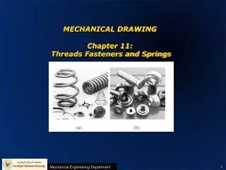
Fundamentals of mechanical drawing • Represent a 3d object in 2d. • Show a scaled representation of an object. • Unambiguously capture all geometric features of an object. • Convey all required information that will allow an object to be produced from raw material. Giant crossbow by Leonardo da Vinci. His ideas have survived 500 years through his detailed sketches.
Representing 3d objects in 2d Orthographic projection: Multiple views of an object from points of view rotated about the object's center through increments of 90°. The views are positioned relative to each other. Isometric projection: One view of an object in which the three axes of space (x,y,z) appear equally foreshortened.
Orthographic projection can provide six planar views of an object.Show multiple views to convey every detail. Center lines are short+long dashed Hidden lines are short dashed
Orthographic projection: each view can be thought of as projections of an object onto the sides of a glass box. Top view Front view Side view Orthographic projections
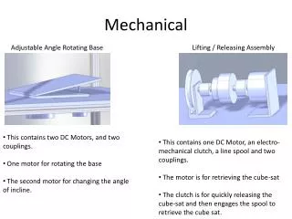
Isometric projections are useful for assembly drawings Nice isometric sketches work well. Assembly drawing Isometric projection with dimensions.
A thick continuous line is used for visible edges and outlines. A thin line is used for hatching, leader lines, short centre lines, dimensions and projections. Dashed lines are used to show hidden edges and important hidden detail, for example wall thickness and holes. Thin chain lines indicate center lines. Center lines are used to identify the center of a circle, cylindrical features, or a line of symmetry. Line types Center lines Hidden lines
Section views reveal hidden details. Section views are indicated by the direction of arrows.
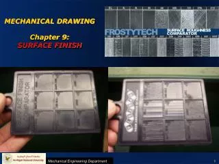
Basics of dimensioning • Always dimension from a common line or surface (datum). This eliminates the addition of measurement or machining inaccuracies that would come from "chain" or "series" dimensioning. • Whenever possible dimension lines should not touch or cross either edge lines or extension lines. • Locate as many dimensions as possible on only one or two sides of an orthographic view. • Indicate on the drawing the unit of measure (inches). Anatomy of a dimension
An excellent tutorial by Richard Link at the US Naval Academy is available from the Senior Design website. Take a look for additional dimensioning tips as well as a checklist of dimensioning Dos and Don’ts.
Suggested drafting or drawing software • AutoCAD • Pro/ENGINEER • Google SketchUp • TurboCAD • QCad • XFig • Typically NOT • Microsoft Word • Paint • Photoshop
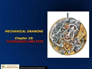
Dimension tolerances are important! Small or “tight” tolerances are expensive. Overall tolerances should typically be specified. One MIL is one thousandth of an inch. 1 MIL=1/1000 inch=0.001 inch=1x10⁻³ inch 1 MIL=0.0254mm=25.4 microns
Fundamentals of mechanical fabrication • Clamping (vice, C-clamps) • Cutting (hack saw, band saw, table saw) • Drilling (drill press, milling machine) • Grinding (grinding wheel) • Bending (press brakes) • Milling (milling machine) • Turning (lathe) • Punching (punch press) • Laser cutting (CNC laser cutter) Hacksaw Drill press Vice Band saw Press brake Milling machine Lathe
Big tip: Keep your mechanical design as simple as possible! • Whenever possible use off-the-shelf components. • Buy a box (“electronics enclosure”) instead of making one. • Erector set approach: bolt simple parts together to create more complex structures. • If you must have a part fabricated then keep the design as simple as possible! • Straight edges are much easier to cut than curved edges. • Few edges are better than many (rectangles instead of pentagons). • Round holes are easier to drill than square holes!! KISS principle Solid block with a thru-hole NO! YES!
Erector-set approach • - Simple parts can be easily cut and drilled from pre-formed raw material • Drill and tap simple parts to join them together with bolts and nuts. • Complex structures can be fabricated from simple components.
Excellent sources for off-the-shelf components • Home Depot • Lowes, Ace Hardware, WalMart • McMaster-Carr • Grainger supply • Small-Parts • Cole-Parmer • DigiKey • Jameco Electronics
Mechanical DesignCritical steps before fabrication • Create a mental picture of the final product. • Determine overall dimensions. Sketch an isometric view. • List each part required (bolts, nuts, brackets, bearings, hinges, motors, etc). • Determine which parts can be purchased off-the-shelf. (Hint: as many as possible!) List them in a table that indicates the vendor, vendor part #, description (size, thread type, etc), quantity needed, and price. • Create multi-view drawings for each part that must be cut, drilled, and/or machined, or modified in any way. • Create assembly drawings that show how each part fits together to produce the final product. • If a machinist is doing any of the fabrication then have your plans reviewed by a knowledgeable engineer (Prof Kay). • Begin fabrication. If a machinist is doing the work for you then be available to answer questions. Provide your contact information (cell phone number) with your plans.
Use engineering paper. Create a mental picture of the final product. Determine overall dimensions. Sketch an isometric view. Mechanical Drawing (1932) by Irene Rice Pereira
List each part required (bolts, nuts, brackets, bearings, hinges, motors, etc).
Determine which parts can be purchased off-the-shelf. (Hint: as many as possible!) List them in a table that indicates the vendor, vendor part #, description (size, thread type, etc), quantity needed, and price.
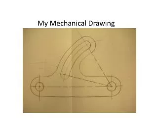
Create multi-view drawings for each part that must be cut, drilled, and/or machined, or modified in any way. HINT: Sketch the orthographic views of each part on paper before drawing them with CAD software.
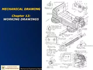
Create assembly drawings that show how each part fits together to produce the final product. Sometimes good sketches make fine assembly drawings.
Another example of an assembly drawing created by an ECE158 student (AutoCAD). Illustration of the mechanomyogram sensor showing the two accelerometers and lead wire innervations.
Mechanical DesignCritical steps before fabrication • Create a mental picture of the final product. • Determine overall dimensions. Sketch an isometric view. • List each part required (bolts, nuts, brackets, bearings, hinges, motors, etc). • Determine which parts can be purchased off-the-shelf. (Hint: as many as possible!) List them in a table that indicates the vendor, vendor part #, description (size, thread type, etc), quantity needed, and price. • Create multi-view drawings for each part that must be cut, drilled, and/or machined, or modified in any way. • Create assembly drawings that show how each part fits together to produce the final product. • If a machinist is doing any of the fabrication then have your plans reviewed by a knowledgeable engineer (Prof Kay). • Begin fabrication. If a machinist is doing the work for you then be available to answer questions. Provide your contact information (cell phone number) with your plans.
Machinists as skilled professionals • Will charge between $60 and $120 per hour. • May charge a minumum of one day’s work. • Must be able to understand your fabrication plan. If not then it costs money! • In the US machinists usually prefer English units (inches). • If you have a friend who is a machinist then ask them for advice to improve your fabrication plan. • The machinists in the basement of Tompkins Hall are available for complex fabrication procedures that you might not be able to accomplish yourself. They are not ECE Senior Design instructors. Do not ask them to design your project for you. They are professionals and their time is important. • If you would like the Tompkins Hall machinists to fabricate a necessary component of your project then follow the machine shop procedures available from the Senior Design Course website. When your fabrication plan is complete it must be certified by Prof Kay. Once it is certified you may submit your fabrication plan and drawings to the Tompkins Hall machinists.
Remember: Anyone should be able to build your device using your fabrication plan …. even 500 years in the future! Questions? Flying machine by Leonardo da Vinci.