Download
1 / 33
340 likes | 795 Views
Module G1 Electric Power Generation and Machine Controls. James D. McCalley. Overview. Energy transformation into electrical form Generation operation Revolving magnetic field Phasor diagram Equivalent Circuit Power relationships Generator pull-out power Excitation control

E N D
Module G1Electric Power Generation and Machine Controls James D. McCalley
Overview • Energy transformation into electrical form • Generation operation • Revolving magnetic field • Phasor diagram • Equivalent Circuit • Power relationships • Generator pull-out power • Excitation control • Turbine speed control
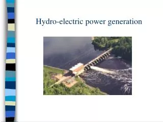
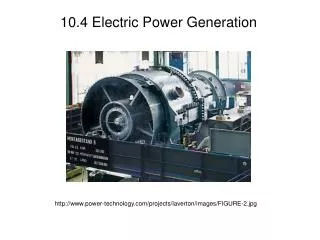
Energy Transformation • Transformation processes: • Chemical • photovoltaic • electromechanical • Electromechanical: conversion of energy from coal, petroleum, natural gas, uranium, water flow, geothermal, and wind into electrical energy • Turbine-synchronous AC generator conversion process most common in industry today
Click on the below for some pictures of power plants and synchronous generators ISU Power Plant http://powerlearn.ee.iastate.edu/library/html/isupp39.html ISU Power Plant synchronous generator http://powerlearn.ee.iastate.edu/library/html/isupp1.html Ames Power Plant http://powerlearn.ee.iastate.edu/library/html/amespp34.html Ames Power Plant synchronous generator http://powerlearn.ee.iastate.edu/library/html/amespp1.html
Feedback Control Systems for Synchronous Generators • Turbine-generator basic form • Governor and excitation systems are known as feedback control systems; they control the speed and voltage respectively
Synchronous Machine Structure Phase A STATOR (armature winding) ROTOR (field winding) + N Phase B + DC Voltage S The negative terminal for each phase is 180 degrees from the corresponding positive terminal. + Phase C A Two Pole Machine (p=2) Salient Pole Structure
Salient Pole Construction Smooth rotor Construction
Synchronous Machine Structure N S S N A Four Pole Machine (p=4) (Salient Pole Structure)
Generation Operation • The generator is classified as a synchronous machine because it is only at synchronous speed that it can develop electromagnetic torque • = frequency in rad/sec • = machine speed in RPM • p = number of poles on the rotor of the machine
For 60 Hz operation (f=60) No. of Poles (p) Synchronous speed (Ns) ------------------- ----------------------------- 2 3600 4 1800 6 1200 8 900 10 720 12 600 14 514 16 450 18 400 20 360
Fact: hydro turbines are slow speed, steam turbines are high speed. Do hydro-turbine generators have few poles or many? Do steam-turbine generators have few poles or many? Fact: salient pole incurs significant mechanical stress at high speed. Do steam-turbine generators have salient poles or smooth? Fact: Salient pole rotors are cheaper to build than smooth. Do hydro-turbine generators have salient poles or smooth?
Generation Operation • A magnetic field is provided by the DC-current carrying field winding which induces the desired AC voltage in the armature winding • Field winding is always located on the rotor where it is connected to an external DC source via slip rings and brushes or to a revolving DC source via a special brushless configuration • Armature winding is located on the stator where there is no rotation • The armature consists of three windings all of which are wound on the stator, physically displaced from each other by 120 degrees
Synchronous Machine Structure Phase A • voltage induced in phase • wdgs by flux from • field wdg • current in phase wdgs • produces flux that • also induces • voltage in phase • wdgs. + N Phase B + DC Voltage S + Phase C
Generation Operation: The revolving magnetic field • = flux associated with the revolving magnetic field which links the armature windings. It will have a flux density of B. • At any given time t, the B-field will be constant along the coil. • By Faraday’s Law of Induction, the rotating magnetic field will induce voltages phase displaced in time by 120 degrees (for a two pole machine) in the three armature windings • Let’s consider just the A-phase.
Generation Operation: The revolving magnetic field (cont’d) If each of the three armature windings are connected across equal impedances, balanced three phase currents will flow in them producing their own magnetic fields = = • = resultant field with associated flux obtained as the sum of the three component fluxes is the field of armature reaction • The two fields represented by and are stationary with respect to each other • The armature field has “locked in” with the rotor field and the two fields are said to be rotating in synchronism • The total resultant field = +
Generation Operation:The phasor diagram • From Faraday’s Law of Induction, a voltage is induced in each of the three armature windings: where N = number of winding turns • All voltages, ,lag their corresponding fluxes, ,by 90 degrees • The current winding a, denoted by , is in phase with the flux it produces
Generation Operation: The equivalent circuit model • Develop equivalent model for winding a only; same applies to winding b and c with appropriate 120 degree phase shifts in currents and voltages given a balanced load
Generation Operation: The equivalent circuit model (cont’d) Ia jXs Ef Zload Vt
Generation Operation: The equivalent circuit model (cont’d) You can perform per-phase equivalent analysis or you can perform per-unit analysis. In per-phase, Ef and Vt are both line to neutral voltages, Ia is the line current, and Z is the impedance of the equivalent Y-connected load. In per-unit, Ef and Vt are per-unit voltages, Ia is the per unit current, and Z is the per unit load impedance.
Leading and Lagging Generator Operation Let From the equivalent circuit, So here we see that
Leading and Lagging Generator Operation Assign Vt as the reference: Then, So here we see that This gives an easy way to remember the relation between load, sign of current angle, leading/lagging, and sign of power angle.
Leading and Lagging Generator Operation Circle the correct answer in each column Inductive load Capacitive load ----------------------------------------------------------------
Phasor Diagram for Equivalent Circuit Ia jXs Ef Zload Vt From KVL:
Phasor Diagram for Equivalent Circuit This equation gives directions for constructing the phasor diagram. 1. Draw Vt phasor 2. Draw Ia phasor 3. Scale Ia phasor magnitude by Xs and rotate it by 90 degrees. 4. Add scaled and rotated vector to Vt Ef jXsIa jXsIa Vt Ia Try it for lagging case. XsIa
Phasor Diagram for Equivalent Circuit This equation gives directions for constructing the phasor diagram. 1. Draw Vt phasor 2. Draw Ia phasor 3. Scale Ia phasor magnitude by Xs and rotate it by 90 degrees. 4. Add scaled and rotated vector to Vt You do it for leading case.
Phasor Diagram for Equivalent Circuit Let’s define the angle that Ef makes with Vt as For generator operation (power supplied by machine), this angle is always positive. For motor operation, this angle is negative.