Download
1 / 26
270 likes | 461 Views
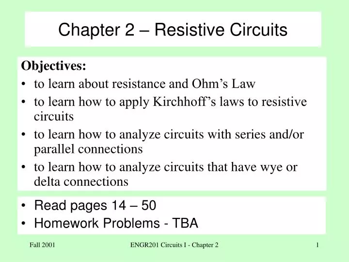
Chapter 2 – Resistive Circuits. Objectives: to learn about resistance and Ohm’s Law to learn how to apply Kirchhoff’s laws to resistive circuits to learn how to analyze circuits with series and/or parallel connections to learn how to analyze circuits that have wye or delta connections.

E N D
Chapter 2 – Resistive Circuits • Objectives: • to learn about resistance and Ohm’s Law • to learn how to apply Kirchhoff’s laws to resistive circuits • to learn how to analyze circuits with series and/or parallel connections • to learn how to analyze circuits that have wye or delta connections • Read pages 14 – 50 • Homework Problems - TBA ENGR201 Circuits I - Chapter 2
Resistance - Definition • Resistance is an intrinsic property of matter and is a measure of how much a device impedes the flow of current. • The greater the resistance of an object, the smaller the amount of current that will flow for a given applied voltage. • The resistance of an object depends on the material used to construct the object (copper has less resistance than plastic), the geometry of the object (size and shape), and the temperature of the object. (R = L/A) ENGR201 Circuits I - Chapter 2
Resistance – Applications • Sometimes we want to minimize the resistance of an object (in a conductor, for instance). • Sometimes we want to maximize the resistance (in an insulator). • Sometimes we to relate the resistance of the object to some physical parameter (such as a photoresistor or RTD). • Sometimes we want to precisely control the resistance of an element in order to influence the behavior of a circuit such as an amplifier. ENGR201 Circuits I - Chapter 2
Resistance - Sizing • Resistors come in all shapes and sizes (see Figure 2.1 in your text). However, several common parameters are used to characterize resistors: • ohmic value (nominal) measured in Ohms (), • maximum power rating measured in Watts (W), and • precision (or tolerance) measured as a percentage of the ohmic value. ENGR201 Circuits I - Chapter 2
Ohm’s Law I = 0.5A I = 1A 12W 6W 12V 12V Ohm’s Law - describes the relationship between the current through and the voltage across a resistor. Different devices connected to a power source demand different amounts of power from that source. That is, different devices present differing amounts of loading. The 6w bulb offers more resistance to the flow of current than the 12w bulb. ENGR201 Circuits I - Chapter 2
Ohm’s Law – Mathematical Definition R = V/I I = V/R V = IR + V - R I I = 0.5A I = 1A 12W 6W 12V 12V • Rather than specify the load that a device represents in terms of its voltage/power rating, we can specify that load in terms of its resistance. • The smaller the resistance the greater the load (the greater the power demand). R = 12V/0.5A = 24 R = 12V1A = 12 ENGR201 Circuits I - Chapter 2
Example 12W 12V 12W 6V How much current will a 12V/12W lamp demand if 6V is applied to it? How much power is demanded? • A 12w/12v lamp will draw 1A of current: • P = VI 12W = 12V I I = 1A • V = IR (Ohm’s Law) R = 12V/1A = 12 • Therefore, if V = 6V I = 6V/1A = 12 • P = 6v 0.5A = 3W = 0.25 12W. • Since both the voltage and current are halved, the power is cut by a factor of four. ENGR201 Circuits I - Chapter 2
Short & Open Circuits + V - R = V/I I = 0A (air, plastic, wood) I = (wire) 12V 12V V Open Circuit, R = I = 0 regardless of the value of V (NO LOAD) Short Circuit, R =0 V = 0 regardless of the value of I R is the resistance of the device, measured in ohms (). The greater the value of R, the smaller the value of I. ENGR201 Circuits I - Chapter 2
Ohm’s Law – Voltage Polarity & Current Direction + V - I = V/R R • Ohms’ law relates the magnitude of the voltage with the magnitude of the current AND • the polarity of the voltage to the direction of the current. Resistors always absorb power, so resistor current always flows through a voltage drop. ENGR201 Circuits I - Chapter 2
Ohm’s Law - Graphically I = V/R + V - R V I Ohms’ Law can be represented graphically – called a VI characteristic: m = Slope = V/I = R Ideal resistor, VI characteristic ENGR201 Circuits I - Chapter 2
Non-ideal Resistors V Open circuit, slope = (I = 0) I Short circuit, slope = 0 (V = 0) V Pmax I Pmax Practical resistor VI characteristic ENGR201 Circuits I - Chapter 2
Conductance • Resistance is a measure of how much a device impedes the flow of current. Conductance is a measure of how little a device impedes the flow of current. • Resistance and conductance are simply two different ways to describe the voltage-current characteristic of a device. • At times, especially in electronic circuits, it is advantageous to work in terms of conductance rather than resistance ENGR201 Circuits I - Chapter 2
Conductance - Units + V - R = V/I, (ohms) Resistance: + V - G = I/V, S (seimens) Conductance: Old style symbol for conductance Old style units = mho (G = 1/R = R-1) ENGR201 Circuits I - Chapter 2
Resistance – Power Equations I + V - Resistance: R P = VI P = V2/R P = I2R V = IR = I/G P = VI (any device) for a resistor: P = V(V/R) = V2/R or P = (IR)I = I2R P = VI (any device) In terms of conductance: P = V(VG) = V2G or P = (I/G)I = I2/G ENGR201 Circuits I - Chapter 2
Kirchhoff’s Laws Node-A Node-A R R R + - R R R + - • Kirchhoff’s Laws • Kirchhoff’s Current Law (KCL) • Kirchhoff’s Voltage Law (KVL) A node is a “point” in a circuit where two or elements are connected. ENGR201 Circuits I - Chapter 2
KCL Node-A I1-I2+I3-I4 = 0 I1+I3 = I2+I4 I2 I3 R I4 R I1 R + - Kirchhoff’s Current Law • The algebraic sum of all currents at any node in a circuit is exactly zero. • The sum of all currents entering = sum of all currents leaving • We neither gain nor lose current at a node. ENGR201 Circuits I - Chapter 2
KVL A Five loops in the circuit shown are: C B B-C-E-B D A-C-B-A A-D-C-A C-D-E-C E A-D-E-B-A Kirchhoff’s Voltage Law (KVL) A loop is a closed path about a circuit that begins and ends at the same node. However, no element may be traversed more than once. Are there more loops ? ENGR201 Circuits I - Chapter 2
KVL A - V2 + + V3 - + V4 - C + V1 - D B + Vy - + V5 - + V6 - + Vx - E • The algebraic sum of all voltages about any loop in a circuit is exactly zero. • The sum of all increases (rises) = sum of all voltage decreases (drops) • We do not gain or lose voltage if we start and end at the same node. • By KVL: • V2 + V3 - V1 = 0 • -V3 + V4 - Vx = 0 • V1 + Vy - V6 = 0 • Vx + V5 -Vy = 0 • V2 + V4 + V5 - V6 = 0 ENGR201 Circuits I - Chapter 2
EquivalentCircuits I1 I2 + - + - Device #1 Device #2 Vs Vs P1 = VSI1 P2 = VSI2 Two circuits are equivalent if, for any source connected to the circuits, they demand the same amount power. The two circuits “look” the same to the source P1 = P2 VSI1 = VSI2 I1 = I2 If the applied voltage is the same, two equivalent circuits will demand the same amount of current from the source. ENGR201 Circuits I - Chapter 2
Series Resistance a a R1 R2 R3 Rab Rab R4 b b R6 R5 I a R1 R2 R3 I Vab Vab R4 Rab b R6 R5 Series connection (all elements have the same current) Vab = I Rab ENGR201 Circuits I - Chapter 2
Series Resistance a R1 R2 R3 R4 I Vab I b R6 R5 Rab Vab Vab = I Rab By KCL: IR1 = IR2 = … = IR6 = I By KVL: Vab = IR1+ IR2+ IR3+ IR4+ IR5+ IR6 Vab/I = (R1 + R2 + R3 + R4 + R5 + R6) = Rab The equivalent resistance of two or more series-connected resistors is the sum of the individual resistors. ENGR201 Circuits I - Chapter 2
Parallel Resistance I A I Vab R1 R2 R3 R4 R5 Vab Rab B Parallel connection (all the elements have the same voltage) Vab/I = Rab • by KCL: • I = I1 + I2 + I3 + I4 + I5 • I = Vab/R1 + Vab/R2 + Vab/R3 + Vab/R4 + Vab/R5 • I = Vab[R1-1 + R2-1 + R3-1 + R4-1 + R5-1 ] • Vab/I = [R1-1 + R2-1 + R3-1 + R4-1 + R5-1 ]-1 ENGR201 Circuits I - Chapter 2
Parallel Resistance I I Vab R1 R2 R3 R4 R5 Vab Rab Vab/I = Rab Rab = [R1-1 + R2-1 + R3-1 + R4-1 + R4-1 ]-1 Since G = 1/R = R-1 Rab = [G1 + G2 + G3 + G4 + G5]-1 Gab = G1 + G2 + G3 + G4 + G5 ENGR201 Circuits I - Chapter 2
The Voltage Divider Rule (VDR) a R1 R2 R3 I Vab R4 b R6 R5 The total voltage applied to a group of series-connected resistors will be divided among the resistors. The fraction of the total voltage across any single resistor depends on what fraction that resistor is of the total resistance. + V4 - RTOTAL = Rab = R1 + R2 + R3 + R4 + R5 + R6 ENGR201 Circuits I - Chapter 2
The Current Divider Rule (CDR) ITotal Vab R1 R2 R3 R4 R5 I5 The total current applied to a group of resistors connected in parallel will be divided among the resistors. The fraction of the total current through any single resistor depends on what fraction that resistor is of the total conductance. GTOTAL = R1-1 + R2 -1 + R3 -1 + R4 -1 + R5 -1 ENGR201 Circuits I - Chapter 2
CDR – Two Resistors Itotal = I1 + I2 I2 I1 R2 R1 For two resistors: • Observations: • The smaller resistor will have the larger current. • If R1= R2, then I1 = I2 • If R1 = nR2, then I2 = nI1 ENGR201 Circuits I - Chapter 2