Download
1 / 22
630 likes | 2.09k Views
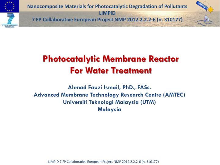
Nanocomposite Materials for Photocatalytic Degradation of Pollutants LIMPID 7 FP Collaborative European Project NMP 2012.2.2.2-6 (n. 310177). Photocatalytic Membrane Reactor For Water Treatment. Ahmad Fauzi Ismail, PhD., FASc. Advanced Membrane Technology Research Centre (AMTEC)

E N D
Nanocomposite Materials for Photocatalytic Degradation of Pollutants LIMPID 7 FP Collaborative European Project NMP 2012.2.2.2-6 (n. 310177) Photocatalytic Membrane Reactor For Water Treatment Ahmad Fauzi Ismail, PhD., FASc. Advanced Membrane Technology Research Centre (AMTEC) Universiti Teknologi Malaysia (UTM) Malaysia
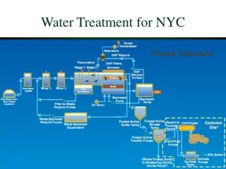
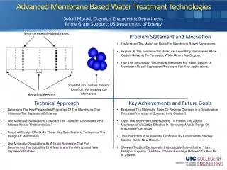
1. Introduction • Separation processes play an important role in the chemical process industries (CPI) for purifying raw materials, recovering products streams and treatment of waste streams. • Membrane technology therefore, can be an alternative technology offering huge energy and operation cost saving. • Membrane is known as one of the most recent and advanced technology in chemical engineering for separation and purification processes. • Photocatalytic membrane reactors (PMRs) represent an interesting alternative technology based on the principles of green chemistry that is useful both in the field of water and air purification and as a synthetic pathway.
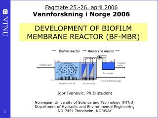
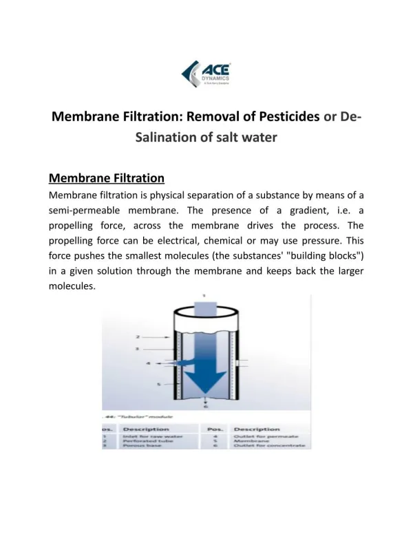
PMR Configurations and Design • A PMR design depends on the process mode (dead end or cross flow, batch or continuous flow, etc.), membrane technique applied (MF, UF, NF, etc.), membrane modules used (flat sheet, hollow fiber, submerged, etc.) or the type of the light source. • Two main groups of PMRs: • Reactors with catalyst suspended in feed solution • (II) Reactors with catalyst supported in/on the membrane Parameters in PMR
Submerged PMR 2 6` 11 • Feed stream • Feed tank • Flow meter • Safety valve • Pump • Pressure gage • Heater • Thermometer • PMR • Mixer • Vapor stream • Cooling tank (tower) • UV light • Hollow fiber module • Permeate tank • Recycle stream 4 5 3 8 12 9 16 13 7 10 14 16 ` 15 Vapor stream polluted water Treated water
Common Configuration of PMR Light source Light source Feed Tank (1) Retentate Retentate ` Membrane module Membrane module Feed Tank Extra Feed Tank Permeate Permeate Fig. 2. PMR utilizing photocatalyst in suspension: irradiation of the membrane module. Fig. 1. PMR utilizing photocatalyst in suspension: irradiation of the membrane module. Light source Retentate Light source Feed Retentate Membrane module Feed Tank Feed Permeate Membrane module Feed Tank Permeate Fig. 4. PMR utilizing photocatalyst in suspension: irradiation of the additional reservoir (photoreactor) located between the feed tank and membrane module. Fig. 3. PMR utilizing photocatalyst in suspension: irradiation of the feed tank.
PMR Schematic Diagram (AMTEC) Heater Electricity supply Motor stirrer Feed Tank N2 and O2 supplement PMR
Previous Studies on Photocatalytic Membrane Reactors **Current study allows in-situ combination of degradation and purification processes in one reactor for large and small molecules under pressure of 1000 kpa
3. Morphological Studies Through the (SEM) image, attachment of nanoparticles was observed and fingerlike and spongy-like was showed.
Morphological Studies • EDX image showed mapping for position of Ti in flat sheet membrane in cross section and surface images by red mappings. Cross section Surface
Pore Characteristics of Nanocomposite Membrane Membrane with this range of mean pore sizes is in UF range and suitable for bilge treatment. The porosity and pore size increased with the increasing filler (MWCNT-TiO2) concentration- FLUX can be greatly increased.
4. Separation Performance The results in this Figure showed that MWCNT-TiO2 improved the performance of nanocomposite membrane in the permeation tests. The FLUX was enhanced with the increasing filler concentration in the nanocomposite membrane
This profile is illustrating rejection results for nanocomposite membrane. As can be seen, the presence MWCNT-TiO2 enhanced the membrane rejection The mixture of hydrophobic filler (MWCNT) and hydrophilic filler (TiO2) increased the rejection of oil (hydrophobic characteristic)
Rejection Improvement • Under pressurized condition, water molecules pass through due to • porosity of the membrane and • hydrophilicity of TiO2. • The hydrophobic oil molecules are retained at the membrane surface due to the hydrophobicity of MWCNTs
GC Characterization • Figure presents the GC chromatogram of the aqueous phase of a O/W sample before UV radiation. • Toxic materials found in the oil sample are indicated in violet color.
GC Characterization After photocatalytic reaction, the concentration of the toxic substances were greatly reduced.
Acknowledgment LIMPID project ““Nanocomposite Materials for Photocatalytic Degradation of Pollutants” EU funded in 7 FP NMP (n.310177) iskindlyacknowledged
The Membrane Team Thank You