Download
1 / 41
410 likes | 575 Views
Review of concepts in Lecture1. By Tom Wilson. Lecture 2 page 1. 1972: T MIXER = 3000 K (SSB) L MIXER = 2 (3 dB loss) T LNA = 20 K G LNA = 10 3 (30 dB gain) So T RX = 3000 K + 40 K + (1/500)T 2. 2005: T MIXER = 50 K (SSB) L MIXER = 1.2 for n =100 GHz T LNA = 5 K G LNA = 10 3

E N D
Review of conceptsinLecture1 By Tom Wilson
Lecture 2 page 1 1972: TMIXER= 3000 K (SSB) LMIXER = 2 (3 dB loss) TLNA = 20 K GLNA = 103 (30 dB gain) So TRX = 3000 K + 40 K + (1/500)T2 2005: TMIXER= 50 K (SSB) LMIXER = 1.2 for n=100 GHz TLNA = 5 K GLNA = 103 So TRX = 50 K + 1.2*5 K + (1.2/(1000)) In addition to the receiver, the atmosphere will add perhaps 20 K extra. In cm wavelength range, less improvement in noise temperatures with time, but most receivers are HEMTs, and we now can build MULTI-BEAM SYSTEMS
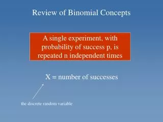
Lecture2 page 2 RECEIVERS Fundamental Relation: Factor of 500 improvement • For broadband measurements, try to keep TSYS small, but also good to have Dn large (bolometers) • For very narrow spectral lines, coherent receivers have Dn as small as you want. for example one can have Dn= 10-9n0 • Note that from Doppler relation, D V= c/n Dn; • At 100 GHz, 1 km s-1=333 kHz
Lecture2 page 3 • Coherent receivers preserve phase, but TRX > hn/k ( at 115 GHz, hn/k = 5.5 K ) from the uncertainty principleDEDt=h • TSYS includes noise from Rx, atmosphere and source • In coherent systems, noise from first stage is most important • Mixer is a non-linear device with signal (ws) and local oscillator (wl)input: (sinwlt + sinwst)2= cos(wlt+wst) + cos(wst-wlt) +...……… ……
Lecture 2, page 3b Arrows here show sampling at twice the frequency F.T. n t t ( )2 F.T. (Must be careful with limits in integral of periodic functions)
Lecture 2 page 4 Lecture 2: Antennas and Calibrations • Single dishes in simple terms • Calibrations • Examples • Single dishes in more formal terms
Lecture 2 page 5 Diameter, D First Null First Sidelobe Simple Diffraction Wavelength, l Can use example of waves passing through an aperture
Lecture 2, page 6 Rectangular Aperture Silver MIT Radiation Lab Series
Lecture2 page 7 FILLED APERTURES: Simple Approach From diffraction q = k l / D=200k l (mm)/D(m), where k is about 1, but can have larger values, but then need a more complex antenna theory Reciprocity: Parameters of transmitting antennas same as those for receiving antennas
Lecture2 page 8 The ALMA 12 meter millimeter/sub-mm prototype radio telescopes in Socorro New Mexico Usually “Filled apertures” means “paraboloids”
Lecture2 page 9 Show that these are equivalent Sn: Flux density TA: This is assuming that the atmosphere of earth has little effect (q0 is in units of arc min and the beam and source are gaussian. Wavelength in cm and TA is corrected for absorption in earth’s atmosphere)
Lecture2 page 10 Descriptive Parameters to characterize antennas: q : Full width to half power beam size WMB: Main beam solid angle hA: Antenna efficiency hB: Beam efficiency
Lecture2 page 11 Measure qB using intense point sources, assume qB is a gaussian. Then WMB = 1.133 qB2 (Gaussians) COMPACT SOURCES: Ag: Geometric area of antenna Effective area Aeff = Ae = hA Ag hA : Antenna efficiency q0 : Observed beam size relation for gaussians qB : Beam qS : Source
Lecture2 page12 Rayleigh-Jeans From Lecture 1: Call TMB the ‘Main Beam Temperature’ MB (q0 is in units of arc min and the beam and source are gaussian. Wavelength in cm) Integrating over the beam Could also integrate over The source (Problem for you: Given the previous relations between TMB , TA and Sn , determine a relation for the ratio of hA to hB in terms of antenna diameter, l and q)
Lecture 3 page 7 APPLICATION OF THESE CONCEPTS NGC7027 (a PNe) has Sn= 5.4 Jy at 1.3 cm. What is the TMB (main beam brightness temperature) if the 100-m FWHP beam size is 43”? Use Where q0 is the telescope beam size in are min. Suppose the “true” gaussian source size is 10”, what is TB (true brightness temperature). Could use (Problem: Repeat for the 30-m, with beam 27’’, wavelength 3.5 mm, flux density 4.7 Jy)
Lecture 3 page 8 Or And get We know from optical spectroscopy that the electron temperature of NGC7027 is Te = 14000 K. Use equation of radiative transfer: To get This is a source which is thermal, so the radiation is free-free or Bremsstrahlung (will discuss in Lecture 3)
Lecture 3 page 9 Venus, at closest approach, has a size of 62”. If we measure an antenna temperature, TA, of 4.2 K with an 8.7’ beam, and a beam efficiency of hB = 0.5, what is the surface temperature of Venus? (Repeat for 3 mm with a 27” beam) Jansky used a telescope with a 30° beam at l= 14.6 m. The maximum intensity was 1.5 .106 Jy in a beam(this was calibrated in the 1970’s; see Lecture 1). What is the TMB? If hB = 0.5, then TA = 2 .105 K >> TRX At 14.6 meters, the whole sky shines brightly, night and day!! Jansky did not detect the Sun, WHY? (see Lecture 1 page 2)
Lecture 3 page 10 SURVEYS: THE SKY HAS 41,252 SQUARE DEGREES Suppose you survey the whole sky with a 30’ beam at 408 MHz. Need 3 samples per beam. (try to characterize a cosine with fewer points). Need 36 samples per square degree, or 1.5 .106 samples in all. Receiver has Dn= 10 MHz. Use t= 10s /point and assume TSKY >> TRX In all measurement time = 1.5 .107 sec = ½ year Now: Try n0= 5 GHz, q= 2.4’, TRX= 50 K with integration time = 10s and Dn= 500 MHz Really more since need to switch to reduce atmospheric noise fluctuation, so DTRMS=10-3 K. If hA = 0.5, on a 100-m telescope, get 1.3 K, TA per Jy, so DSrms = 0.7.10-4 Jy. Detect at 4DTRMS=3 .10-4 Jy = 0.3 mJy. But need 2.3 .108 samples, or 6.5 .105 hours = 74 years. Need MULTIBEAMING
12b More details of antennas B WA is integral over entire power pattern
Lecture2 page 13 Define WA as integral over whole Power Pattern, PN: hB: Fraction of power in main beam used for sources which are extended to about size of main beam. For point sources, use hA
From Lecture 1: The Moon is measured at 3mm wavelength with a 12m telescope. The antenna beamsize is q=50”, less than Moon size of 30’. So the source fills the main beam and we know that the temperature of the Moon is 220K. This should be the main beam brightness temperature, TMB = 220 K. The beam efficiency is hB=80%, so the measured antenna temperature should be TA=0.80*220K=176K. We find it is more since the sidelobes also receive power from the Moon. This is like the situation for CO lines in the millimeters. We need to take this into account. Lecture 2 page 15 Example: Why need mm calibration
Lecture2 page16 Rectangular Aperture Half width To half power First Sidelobe (for a 12m antenna at l=3 mm, at 75” from axis) Silver, MIT Radiation Lab Series
Lecture2 page17 Historical Introduction to Calibration • In centimeters, atmosphere has little effect, and can use flux density transfer from standard sources for calibration • This is by means of a pulsed calibration, injected periodically together with the signal • This was to transfer scale from a known source to the source of interest • Atmosphere had little or no influence • This is not so in the millimeter wavelength range • Water vapor is the larger problem: this has a scale height of 2 km • Oxygen has a scale height of 8 km
Lecture2 page 18 Calibration for Millimeters FROM LECTURE 1: Equation of radiative transfer and Rayleigh-Jeans approximation gave on source off source If use for “on-source minus off-source” get TB: Measured T: Atmosphere T0: Astronomical source Must correct for this loss in the atmosphere
Lecture2 page 19 Carbon monoxide, CO, line frequencies This plot for t225=0.05 Fine structure Lines of neutral Carbon (C I) 225 GHz is not close to any water lines, but The opacity is representative
Lecture2 page20 Thus the source intensity is reduced. In the millimeters, historically the measurements concentrated on spectral lines, especially carbon monoxide CO. To calibrate the very extended emission from molecular clouds, one used the ‘chopper cal’ method. This made use of measurements of a warm absorber, the atmosphere and then (often) a cold absorber.
Lecture2 page 22 Tsky=Tatm(1-e-t) Beff isthe same as hB
(At 1.3 mm, the power in the error beam is about 20% of that in the main beam) Lecture2 page23 Details: Error Beam
Lecture2 page24 30-m Error Beam (Greve et al. 1998 A&A Suppl 133, 271)
Lecture2 page25 The Effect of Feed Legs on the Telescope Beam Pattern Effelsberg 100-m telescope: a classic case of ‘fat feed legs’’
Lecture2 page27 Reflections in the Telescope Reflection is at the feed horn
Lecture2 page28 Instrumental Baseline Ripples Both spectra are ‘signal minus reference over reference’, at different axial focus settings
Lecture2 page29 Observing Strategies • Position Switching • Beam Switching • On the Fly Mapping • Frequency Switching
Lecture2 page30 Beam Switch/Position Switch(Also ‘wobble Switching’) Noise is factor of two larger than in total power spectrum
Lecture2 page31 On-the –Fly Mapping Total integration time, t, for each on-source spectrum is the sum of ton & toff Have ‘n’ on’s for each off For n on’s, spend more time on off source
Lecture2 page32 Frequency Switching more noise in this spectrum, compared to a total power spectrum
Lecture2 page33 Telescope Pointing • Must have fairly intense sources with known positions • These must be small compared to the telescope beam • Could be spectral line or continuum sources, planets, moons of planets, some asteroids
Lecture2 page34 Full Width to Half Power points: The position of the source is most accurately found by determining these locations Could also use a Gaussian fit to the scan, if the signal to noise Ratio is sufficient. This is usually done for continuum measurements. For spectral line pointing, one usually measures at the source peak and 4 points around the peak, usually at the half power points.
Lecture2 page35 Calibration Sources • Even though the chopper calibration gives a value for TA* or TMB, may be additional factors, such as mixer sideband ratio, telescope gain vs elevation effects, pointing errors… • With fixed tuned SSB mixers this is less true, but one may still want to have a system check using a ‘standard’ source. • Not as large a problem with continuum measurements • But using measurements of standard sources allows one to determine an intensity scale that others can relate their measurements to.