Download
1 / 25
260 likes | 563 Views
Connecting the MLC9000 to the Allen Bradley SLC500 via Modbus. Equipment and Software Needed. MLC 9000 BCM with Modbus and appropriate number LCM’s AB SLC 5/03 CPU or higher, Power Supply and Rack 5/03 is smallest CPU to support M0/M1 file transfer ProSoft MCM3150 Modbus Communications Card

E N D
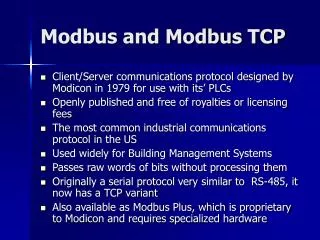
Connecting the MLC9000 to the Allen Bradley SLC500 via Modbus
Equipment and Software Needed • MLC 9000 BCM with Modbus and appropriate number LCM’s • AB SLC 5/03 CPU or higher, Power Supply and Rack • 5/03 is smallest CPU to support M0/M1 file transfer • ProSoft MCM3150 Modbus Communications Card • RSLogix 500 Programming Software for SLC500 • Programming Cable for SLC500 • West.RSS Driver File • Communication Cable between MLC9000 and MCM3150 Card
SLC500 Backplane Communications Basics • SLC 500 is a modular PLC • Racks can be configured with a wide variety of modules • PLC CPU receives information from modules in rack via one of two ways • I/O Transfer • Used with Analog or Digital I/O Modules where small amounts of information are being passed • Block Transfer via M0/M1 Files • Used for large blocks of data • M0/M1 files are local to the module • Information must be transferred form M0/M1 files into usable registers • Process is known as Block Transfer
SLC500 Backplane Communications Basics Integer File Integer File M0 M1 ... ... ... ... Block Transfer Example
Setting Up the ProSoft 3150-MCM • Verify Jumpers are in position for RS485 2-Wire (Factory Default)
Setting Up Communications between PC and SLC500 • From Start Menu, start RSLinx under Rockwell Software • Under Communications, select Configure drivers
Setting Up Communications between PC and SLC500 • From Available Driver Types select 1747-PIC/AIC+ Driver
Setting Up Communications between PC and SLC500 • Set station number to 31, pick open comm. port on PC
Setting Up Communications between PC and SLC500 • Close window then reboot PC to start driver
Loading the Driver for the 3150-MCM From Start Menu, load RSLogix 500
Loading the Driver for the 3150-MCM Select File, then Open and select the directory that West.RSS is stored in.
Loading the Driver for the 3150-MCM • From Menu Bar on Left, Double-Click on IO Configuration • Verify Configuration for correct number of racks and position of modules
Loading the Driver for the 3150-MCM • From Menu on left, under Data Files, double-click on N255 West • Adjust N255:110 to the proper number of loops in the system
Loading the Driver for the 3150-MCM • N255:111-N255:142 Contain the Modbus Addresses for up to 32 loops • Adjust these files to match Modbus Addresses of LCM’s
Loading the Driver for the 3150-MCM • To begin download, first go to communications menu and select System Comms
Loading the Driver for the 3150-MCM • Select PLC to download program to • Select Download
Loading the Driver for the 3150-MCM • Select OK to begin download
Loading the Driver for the 3150-MCM Press Yes to Go Online
Completing Communications between 3150-MCM and MLC9000 MLC9000 to ProSoft 3150-MCM Cable Pin-out (RS485) 3150-MCM MLC 9000 9 5 (A) 1 4 (B) 5 3 (GND) 7 8
Diagnostics on 3150-MCM • Eight indicator lights on module used as communications diagnostics
MLC 9000 Parameters • N250 File used to hold parameters read from MLC 9000 loops 1-16 • N250:XXX-address of parameter to be accessed • Read-Only data, to be used by PLC or HMI for reference • File N251 used for loops 17-32
MLC9000 Parameters • Alarm Words are broken down into sixteen read accessible bits • Bits are accessed through address format N250:XXX/XX
MLC9000 Parameters • N254 File used for data to be written to MLC9000 • N254:XXX-address format used for accessing write data • Data has Read/Write capabilities, can be manipulated by PLC or HMI
MLC9000 Parameters • Control Bits are broken down into 16 Read/Write bits • Parameters are addressed in N254:XXX/XX format