Download
1 / 17
170 likes | 325 Views
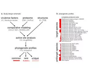
A conceptual design study for a super-ferric PS2. L. Bottura, R. Maccaferri, C. Maglioni, V. Parma, L. Rossi, G. de Rijk, W. Scandale, L. Serio, D. Tommasini GLM - October 8 th , 2007. Motivation. Take an alternative approach to the work of R. Ostojic et al. (1) Leading ideas:

E N D
A conceptual design study for a super-ferric PS2 L. Bottura, R. Maccaferri, C. Maglioni, V. Parma, L. Rossi, G. de Rijk, W. Scandale, L. Serio, D. Tommasini GLM - October 8th, 2007
Motivation • Take an alternative approach to the work of R. Ostojic et al.(1) Leading ideas: • Minimise the variations with respect to the NC baseline • Magnets are iron-dominated, with field quality determined by the shape of the iron pole • Warm magnet bore, the same access as in the NC baseline (e.g. for beam pipe and collimation systems) • Aim at a maximum efficiency in terms of power requirements and operation costs • Reduce AC losses to the minimum that can be reasonably achieved • Place SC coils in locations shielded from beam loads • Conservative design for reliability and robustness • Large operating margins (temperature, current) (1)A Preliminary Analysis of the Options for the Magnet System of the PS2, AT-MEL Technical Note, June 1st 2007
Dipole magnet design Bx [T] By [T] Bmod [T] A + 0.6 - 0.8 1.0 B + 0.4 + 0.2 0.4 C - 0.2 + 0.2 0.3 D 0.0 - 0.7 0.7 Cryostat Superconducting coil D C A B
Comparison of dipole designs Magnet length 3 m Number of magnets 200 Iron weight 10 tons Peak current @ 1.8 T 5300 A Current rise rate 4830 A/s Number of turns 2x10 Inductance 7 mH Peak voltage 34 V Magnet length 3 m Number of magnets 200 Iron weight 15 tons Peak current @ 1.8 T 5775 A Current rise rate 5260 A/s Number of turns 2x9 Inductance 6 mH Resistance 1.7 m RMS Current 3990 A Power consumption 27 kW Peak voltage 41 V
Quadrupole magnet design Bx [T] By [T] Bmod [T] A + 0.6 0.0 0.6 B + 0.6 0.0 0.6 C + 0.1 0.0 0.1 D + 0.1 0.0 0.1 Cryostat Superconducting coil D A C B
Comparison of quad designs Magnet length 1.75 m Number of magnets 120 Iron weight 2.8 tons Peak current @ 16 T/m 4600 A Current rise rate 3830 A/s Number of turns 4x6 Inductance 2.2 mH Peak voltage 8 V Magnet length 1.75 m Number of magnets 120 Iron weight 4.4 tons Peak current @ 16 T/m 1200 A Current rise rate 1000 A/s Number of turns 4x23 Inductance 35 mH Resistance 26.7 m RMS Current 830 A Power consumption 18 kW Peak voltage 67 V
Superconducting cable • Low-loss strand (requires targeted R&D) • Jc = 2500 A/mm2 (below LHC standard) • Deff = 2 m (≈ 3…4 m achieved on LHC strands) • = 0.5 ms (≈ 0.1 ms achieved with resistive barriers on previous productions) • Force-flow cooled cable • Small He inventory • High voltage insulation, possible through classical winding techniques • Stability advantage, robust against perturbations, for reliable operation
Cable design • Dstrand: 0.5 mm • Jc(4.2 K, 5 T): 2500 A/mm2 • Cu:NbTi: 2.7 • Deff: 2 m • : 0.5 ms • Number of strands: 53 • Bnom: 2 T • Tnom: 4.5 K • Inom: 5800 A • Ic: 15900 A • Tcs: 7 K • Iop/Ic: 37 % • Tmargin: 2.5 K • IDspiral: 7.6 mm • ODconductor: 9.6 mm • Ra: 100 Internally cooled cable Prototype from VNIIKP NOTE: other configurations are possible, e.g. a plain CICC or a Nuclotron-like cable
Thermal loads • AC loss calculation • Cycle time 2.4 s (1.1 s ramps, 0.1 s plateaux) • MB AC loss average over a cycle • Total of 0.44 W/m of magnet (1.3 W/magnet) • Equal split among strand coupling, cable coupling and filament hysteresis • MQ AC loss average over a cycle • Total of 0.40 W/m of magnet (0.7 W/magnet) • Half originated from strand and cable coupling, half from filament hysteresis • Take for both MB and MQ a design value of 1 W/m of magnet for cooling analysis (safety factor 2 to 3 with respect to estimates) • Beam losses are assumed to be small, as the coil is hidden by the iron. • Take a design value of 1 W/m of magnet for cooling • The cryostat surrounds the coils, requires careful engineering, but there is space to introduce thermal screens (20 mm) • Take a thermal load design value of 1 W/m of magnet for cooling
Magnet cooling • Supercritical cooling of the magnets (inlet at 4.5 K, 5 bar, 5 g/s) • MB • Thermal loads: 7.3 W • Temperature increase: 0.2 K • Pressure drop: 0.1 bar • Pumping work: 0.25 W/magnet (negligible) • MQ • Thermal loads: 4 W • Temperature increase: < 0.1 K • Pressure drop: 0.03 bar • Pumping work: 0.1 W/magnet (negligible)
Cryoplant design • Thermal loads • Static load on magnets: 1W/m @ 4.5 K • Static load on transfer lines: 0.2 W/m @ 4.5 K • Liquefaction: 1.5 g/s of Lhe for 6x5 kA current leads • Dynamic load on magnets: 2 W/m @ 4.5 K • Thermal shield: approximately5 kW @ 75 K • Nominal capacity required: 3.3 kW @ 4.5 K • Installed capacity: 5 kW @ 4.5 K • Warm power requirements (250 Wwarm/Wcold) : • Electrical power: 1.25 MW • Cooling requirement: 1.25 MW
Assumptions for cost analysis • SC magnet construction: • Iron yoke (warm): 6.6 CHF/kg • Superconducting coil: 250 CHF/kg • Cryostat: 25 kCHF/magnet • Magnet testing: 10 kCHF/magnet • SC auxiliaries: • Quench detection & protection: 1 MCHF total • Current leads and bus-bars: 3 MCHF total • Power converters costs are taken identical to previous analysis • Cooling and ventilation costs are assumed equal for NC and SC because of the reduced SC power requirement • Buildings cost for cryogenic plant are assumed to be reduced for the lower installed power • Operation: • Cryogenic operation is run by CERN (as power converters) • Electricity is quoted at 40 CHF/MWh
NC magnets Dipoles: 30 MCHF Quadrupoles: 9 MCHF Testing: 1 MCHF Auxiliaries: 1.5 MCHF Power converters Total: 19.3 MCHF Cooling and ventilation Total: 1.1 MCHF Total cost: 61.9 MCHF SC magnets Dipoles: 21.3 MCHF Quadrupoles: 6.6 MCHF Testing: 3.2 MCHF Auxiliaries: 4 MCHF Cryogenics Plant + lines: 13.5 MCHF Building: 3.1 MCHF(1) Power converters Total: 15 MCHF Cooling and ventilation Total: 1.1 MCHF(2) Total cost: 67.8 MCHF Cost of NC PS2 by courtesy of M. Benedikt Cost comparison - investment (1) Scaled to 1/2 of estimate for the 15 kW plant (2) Assume the same as for NC magnets, benefiting from lower power requirement
Installed power of NC PS2 by courtesy of M. Benedikt Power requirements
NC magnets Energy: 14.6 MW * 6000 hrs/yr Energy cost(1): 3.8 MCHF/yr Total cost: 3.8 MCHF/yr SC magnets Energy: 7.6 MW * 6000 hrs/y Energy cost(1): 1.9 MCHF/yr Cryo maintenance: 0.3 MCHF/yr Total cost: 2.2 MCHF/yr Cost of NC PS2 by courtesy of M. Benedikt Cost comparison - operation (1) Assuming 40 CHF/MWh
Is HTS an option ? • The use of HTS materials would affect: • Construction cost • Coil more expensive, cryostat simpler, smaller cryogenic installation (at best liquid nitrogen) • Operation • A larger margin to improve robustness • The cryogenic load can be removed at higher operating temperature, which requires lower installed power • Changes in the cost estimates for the SC PS2: • Investment cost reduced by 5 … 10 MCHF • Installed power reduced by 1 MW • Operation cost reduced by 0.25 MCHF/year Marginal gain with respect to previous figures (10 %) could be beneficial for the overall reliability
Summary • A SC-superferric PS2 is approximately 6 MCHF more expensive than a NC PS2 (≈ 3 % of the total value) • Magnets are about 6 MCHF cheaper (50 % less iron) • Power converters are 4 MCHF cheaper • Cryogenics + buildings cost 16 MCHF • A SC-superferric PS2 consumes a projected 7.6 MW, about half of the power required by a NC PS2, i.e., 14.6 MW • Operation costs are in consequence significantly lower, by 1.6 MCH/year at the assumed electricity cost of 40 CHF/MWh. This advantage scales with energy cost.