Download
1 / 24
270 likes | 501 Views
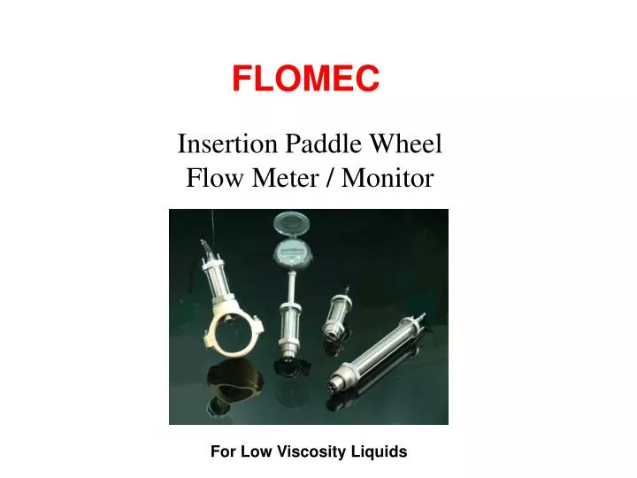
FLOMEC. Insertion Paddle Wheel Flow Meter / Monitor. For Low Viscosity Liquids. FLOMEC. Introduction. Insertion Paddle Wheel Flow Meter / Monitor Cost effective. Simple means of measuring the flow. Wide range of low viscosity liquids. Operating principle

E N D
FLOMEC Insertion Paddle Wheel Flow Meter / Monitor For Low Viscosity Liquids
FLOMEC Introduction • Insertion Paddle Wheel Flow Meter / Monitor • Cost effective. • Simple means of measuring the flow. • Wide range of low viscosity liquids. Operating principle Flow passes through a pipe causing the rotor to spin. Magnets installed in the rotor pass by pulse sensors within the transducer body & inturn this produces frequency outputs proportional to flow rate.
Flomec Robust Features • Insertion Paddle Wheel Flow Meter / Monitor • Durable PVDF or PEEK rotor. • Graphite - PTFE impregnated peek bearing. • Precision ground stainless rotor shaft. • 316 stainless steel body.
Flomec Paddle Wheel Features • All stainless steel construction • Dual independent pulse outputs • Direct input to PLC and Computer • High pressure submersible design • Pipe sizes 1.5” to 100” (40-2500mm) • Electrical interference immunity • Minimal pressure loss • Simple to install • Low installed cost • European CE compliant.
Flomec Paddle Wheel Options • High temperature to 4000F (2000C) • Reed switch option for hazardous area operation (intrinsically safe) • Integral or remote high speed preset batch controller • Optional Bi-directional discriminator • output • Non magnetic rotor option for liquids containing ferrous suspensions.
Flomec Innovative Design The metering head of the Paddle Wheel is shaped to encourage a conditioned flow profile at the aerofoil shaped rotor. The combination of these unique features extends the linear measuring range to cover flow velocities from 1.0 - 33 ft/sec (0.3 - 10 metres/sec), without creating flow cavitation. Paddle Wheel Flow Conditioning at Metering Head
Flomec Paddle Wheel Outputs • Standard, two independent pulse outputs • Suitable for direct input to a wide range of ancillary instruments, Z3 Totalizer, PLC's and computers. • Both pulse outputs are rotor magnet activated. • High level of immunity to electrical interference experienced with most other transducers of this kind.
Flomec Outputs High Level Voltage Pulse - A self generating pulse output requiring no power source, produces a strong 1.5 volt output spike of approx. 10 micro seconds duration with no dependence on rotor speed. Square Wave Output - An open collector pulse output produced by a solid state Hall Effect device. This three wire device requires 5-24VDC excitation voltage and produces a high resolution NPN square wave conditioned output.
ALIGNMENT SLOT TO PARRALLEL PIPE LOCK D Flomec Installation General Arrangement Standard Installation Examples of insertion depth D: For 40mm pipe ID ( D= 5.0 mm ) For 50mm pipe ID ( D= 6.25 mm ) For 100mm pipe ID ( D= 12.5 mm ) For 400mm pipe ID ( D= 50.0 mm ) Z3 Rate Totaliser
2" ball or gate isolation valve. Flomec Installation Hot Tap Installation DOR Paddle Wheel
Major obstructions such as pumps, valves, reducers or strainers to be kept well outside the straight run pipe sections 10 pipe dia. minimum 25 pipe dia. prefered 5 pipe dia. min. 10 pipe dia. prefered FLOW 12 o’clock 2 o’clock Other positionsaround the pipe are acceptable Flomec Installation Installation Straight Piping Requirements 10 o’clock Orientation Mount on either the 2, 10 or 12 o’clock positions of the pipe. If there is any likelihood of air entrainment in a horizontal pipe do not locate the flow transducer in the 12 o’clock position.
Flomec Fluid Flow in Pipes Factors which affect the flow of a fluid in a pipe include:- - Velocity of the the fluid (mean velocity) - Viscosity of the fluid - Density of the fluid - Diameter of the pipe - Pipe friction where the fluid is in contact with the pipe. Fig. 1 Ideal fluid velocity profile If we ignore the effects of viscosity and the pipe friction, a fluid wouldtravel through a pipe in a uniform velocity across the diameter of thepipe. The 'velocity profile' would appear as in Fig 1.
Flomec Fluid Flow in Pipes However, this is very much an 'ideal' case and, in practice, viscosity effects the flow rate of the fluid and works together with the pipe friction to further decrease the flow rate of the fluid near the pipe wall. This can be represented in Fig 2. The most important of the factors effecting fluid flow in pipes can be pulled together in one dimensionless quantity to express the characteristics of flow. This is known as the Reynolds Number. Fig. 2 Real fluid velocity profile
Fluid Flow in Pipes At very low velocities, the dynamic force will be low and, therefore, the Reynolds Number will be small. Similarly, a high viscosity fluid will result in low Reynolds Number. This will result in viscous forces holding back the fluid flow at the pipe walls with the highest fluid velocity at the centre of the pipe. This is similar to Fig 2. Except that the velocity profile is a parabola (see Fig 3.). It is known as laminar flow and normally occurs at Reynolds Numbers below 2000. Fig. 3 Laminar Flow Flomec
Fluid Flow in Pipes When Reynolds Numbers are above 2000 i.e. high velocities and/or low viscosities, the flow breaks up and Turbulent flow occurs with a much flatter velocity profile (see Fig. 4). Fig. 4 Turbulent flow velocity profile In the process world, unless very viscous fluids are being piped, turbulent flow is the norm. This is certainly the case for steam where Reynolds numbers well in excess of 2000 are encountered. Flomec
Flomec Installation Guidelines
Flomec Applications Wide Application Typical industry applications include: HVAC - Hot and chilled water, Fire systems and Thermal energy monitoring. Municipal - Water distribution, Water management and Water treatment. Irrigation - Water management. Water treatment- Chlorination, Desalination and mechanical filtration plants, Chemical injection systems. Refineries - Primary flow additive injection, Fire and cooling systems. Power Generation- Boiler feed water, Steam condensate, Process water and water balancing. Chemical - Process and cooling tower water, Chemical and water batching. Others - Cement Mfg, Diesel fuel transferring, Flow testing, Fire truck and Hydrant flow monitoring, Food processing, Pulp/paper, Mining.
Flomec Specifications Model Prefix DP-490 DP-525 Suit Pipe Sizes 40 - 900 mm (11/2" - 36") 50 - 2500 mm (2" - 100") Process Connections R11/2" Male or 11/2" NPT male R2" Male or 2" NPT male Body & O-ring Material 316L stainless steel body & rotor shaft, FPM O-rings Rotor Material PVDF ( 100 deg C ) or PEEK ( 200 deg C ) Velocity Range 0.3 - 10 metres / sec. (1.0 - 33 ft / sec.) Flow Range 0.25 - 6300 litres / sec. (4 - 99600 USGPM) Linearity & Repeatability Linearity typically +1.5%, Repeatability +1%, with well established flow profile Maximum Pressure 80 bar (1200 PSI)
Flomec Specifications Model Prefix DP-490 DP-525 Temperature Ranges Standard -40C0 to 1000 C (-400to 2120 F) plus option to 2000C (4000F) Outputs (standard)transmission to 1000m(3300 ft) max. Voltage Pulse self generated 1.5V x 10s (2 wire) 200 - 240hz max. Open Collector NPN 5 - 24VDC square wave (3 wire) 200 - 240hz max. Outputs (optional) Reed Switch (2 wire) 66 - 80hz max. [can be used as I.S. with barrier] Non magnetic rotor + Hall Effect output (for liquids with ferrous impurities) High temperature voltage pulse output to 2000C (4000F) Quadrature output (dual Hall Effect output with 900phase shift). Conduit Entry 3/8" NPT or PG9 conduit thread (M16 x 1.5 on terminal box option) Cable 3 metres (10ft) screened 5 core as standard, longer lengths are optional. Mounting Requirements BSP / NPT service saddle Shipping Weights 1.3 kg (3lbs) 1.5 kg (3.3lbs)
Flomec Ordering Information Insertion Paddle Wheel DP-490 / DP-525 DP-490 40-900mm pipes (1.5" - 36") - 1 1/2" BSP/NPT process connections. DP-525 50-2500mm pipes (2" - 100") hot-tap version - 2" BSP/NPT process connections. Body Material 316 stainless steel. Rotor Material • 2 =PVDF / St. St. ( max 100 deg C ) • 4 =Peek / St. St. ( max 200 deg C ) • X =Special ( on request ) Sealing Material F= FPM ( standard ) N =NBR P = PTFE ( encapsulated FPM ) E = EPR ( for Ketones only ) Mechanical Connection DP-490 R8 = R1 ½” male R9 = R2 male N8 = 1 ½” NPT male N9 =1000C (1850F – standard ) DP-520 R9 = BSPT male N9 = 2” NPT male
Ordering Information Flomec Insertion Paddle Wheel DP-490 / DP-525 Order Example: DOR-52 4 F R9 H5 00 Output / Electrical Connections F1 = NPN OC + 1.5V – pulse + 3 m cable ( standard ) F2 =NPN OC + 1.5V – pulse + 10 m cable F3 = NPN OC + 1.5V – pulse + 20 m cable F4 = NPN OC + 1.5V – pulse + 50 m cable F5 = NPN OC + 1.5V – pulse + terminal box on stem kit F6 = NPN OC + 1.5V – integral electronic ZOD on stem kit N5*= NPN OC + terminal box on stem kit + high temp. sensor N6*= NPN OC + integral electronic ZOD on stem kit + high temp. sensor R1 = Reed switch + 3 m cable R2 = Reed switch + 10 m cable R3 = Reed switch + 20 m cable R4 = Reed switch + 50 m cable R5 = Reed switch + terminal box on stem kit Q1 = 2 x NPN OC + 3 m cable Q2 = 2 x NPN OC + 10 m cable Q3 = 2 x NPN OC + 20 m cable Q4 = 2 x NPN OC + 50 m cable Q5 = 2 x NPN OC + terminal box on stem kit E1 = Non magnetic rotor for ferrous media, NPN, 3 m cable E2 = Non magnetic rotor for ferrous media, NPN, 10m cable E3 = Non magnetic rotor for ferrous media, NPN, 20m cable E4 = Non magnetic rotor for ferrous media, NPN, 50m cable T5*= Non magnetic rotor for ferrous media, ind. Coil, terminal box on stem kit H5*= High temp. inductictive coil, terminal box on stem kit, + 200 deg.C XX = Special option ( specified in clear text, consult factory ) • *Denotes only possible • with PEEK rotor
Flomec Ordering Information Paddle Wheel Meter DP-490 / DP-525 - cont’d Electronics -00 =Frequency output only 3 metres cable - standard Only for output F6 & N6 Z1 = Electronic ZOD-Z1 Z3 = Electronic ZOD-Z3 Z5 = Electronic ZOD-Z5 B1 = Electronic ZOD-B1 XX = Special option ( specified in clear text ) Special options None = Without options Y = Special option (specified in clear text )
Flomec Options Paddle Wheel Rate / Totalisation Options The FRT12 Series of Flow Rate Totalisers are field mount or remote instruments for accurate flow rate indication and totalisation of flow. The self powered FRT12 interfaces direct to the Paddle Wheel without the need for external power. Alternatively it can be loop powered via an optional 4-20mA output. The instrument is housed in a robust plastic enclosure that is completely watertight to IP67 (Nema 4X) classifications. Programming is done via the front keypad including flow K-factors, Engineering unit selection, 4-20 mA analog Output Spans,High and Low Flow Alarms & linearisation.