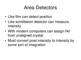
Download
1 / 16
160 likes | 259 Views
Light Detectors (abbreviated version, sort of). Human Eye Phototubes PMTs CCD etc. Human Eye. Cones: less sensitive 3 color receptors highest density near fovea. Rods: more sensitive no color highest density away from fovea. Phototubes.

E N D
Light Detectors (abbreviated version, sort of) Human Eye Phototubes PMTs CCD etc.
Human Eye Cones: less sensitive 3 color receptors highest density near fovea Rods: more sensitive no color highest density away from fovea
Phototubes Example of an early phototube attached to a telescope
Photomultiplier Tubes (these 2 figures from Hamamatsu’s web page at http://learn.hamamatsu.com/articles/photomultipliers.html) Not used much in astronomy today, but common in Cherenkov detectors in particle physics
Microchannel Plates (like a 2-D array of PMTs)
Charge Coupled Devices - CCDs Front-lit CCD - gate block light! Back-lit CCD
In the upper figure, a positive voltage on one of the gates attracts and confines the electrons. By increasing the voltage in the next gate while reducing that in the original gate, the electrons are effectively “handed off” to the next gate. By sending voltage pulses to the gates in groups of three, all the charge packets can be moved to the side.
Once a column of charges has reached the edge of the chip, they are then read out in the perpendicular direction. These are then sequentially dumped onto a capacitor (small charge storage device), which changes its voltage. The voltage is detected and this number sent out as the “signal” that hit that one picture element, or pixel. This readout process can be slow, especially for large chips. While reading out, the chip is still “busy” and light sensitive, s no exposing can be done.
The charge of each x,y pixels is “read out” by passing it through an amplifier to produce a voltage (think of it as reading the voltage across a capacitor with the electrons stored on one plate). This voltage must them be converted into a digital signal using an Analog-to-Digital (A-to-D) Converter. Each Digital Number (DN) represents a certain number of electrons, and is referred to as the Analog-to-Digital Unit (ADU). The number of electrons per ADU is the gain. Full Well - each diode has a maximum number of electrons it can hold before it is full or “saturated”. Charge may leak to neighboring pixels even before saturation is reached. Dynamic Range - the largest number that can be represented, compared to the smallest non-zero value (i.e. unity). This may be set by the full well capacity or by the AD converter. As these are digital devices that work in binary numbers (zero or one) they will always be: where n is some integer (and the -1 is to get an ADU=0). We will come back to this topic later.
To speed up the process, it is possible to mask half the pixels with a reflective material, expose the naked ones, shift then under the masked pixels, and read them out while the next exposure begins. Such schemes are useful for video cameras, when rapid readout is essential. But the blockage of 50% of the incoming light renders them less suitable for low-light applications. Interline transfer CCD Screen transfer CCD
Upper Left – 800 x 800 pixel CCD like the ones used on the cameras of the Galileo spacecraft. Upper Right, the same chip under 20x magnification. Lower Left, under 60x magnification. Here the structure of the individual pixels is becoming apparent. Lower Right: Jupiter’s Great Red Spot from Galileo.
CCDs are “black & white” devices. To get color: Successive images, each through a different filter Deposit colored filters right on the chip! (these images from Santa Barbara Instrument Group (SBIG))
HgCaTe Photoconductors (currently the main 2-D near-IR detector) Often the sensitivity is given in terms of the Noise Equivalent Power (NEP) - that minimum detectable power (required to give a signal-to-noise ratio of 1) per square root of the bandwidth. The Detectivity D is the reciprocal of the NEP.
Bolometers Generally, these are meant to detect “everything” Uses a photoconductive material painted “black” Photons hitting it are absorbed, changing the temperature of the material, and its resistance. Usually operated at temperatures below 2 Kelvins. A commonly-used detector for far-IR photons. (these images from the Herschel Space Telescope web site)
Historical Note The original Palomar Sky Survey used the 48-inch Samuel Oschin Schmidt, and photographic plates that were 14 inches on a side!! This covered much more of the sky - 6 degrees square - than any puny CCD could. However, the Quasar Equatorial Team (QUEST) used a mosaic of 112 CCDs to cover 4 degrees squared. This was the instrument astronomer Mike Brown and others used to discover the biggest objects in the solar system beyond the orbit of Neptune.