Download
1 / 1

E N D
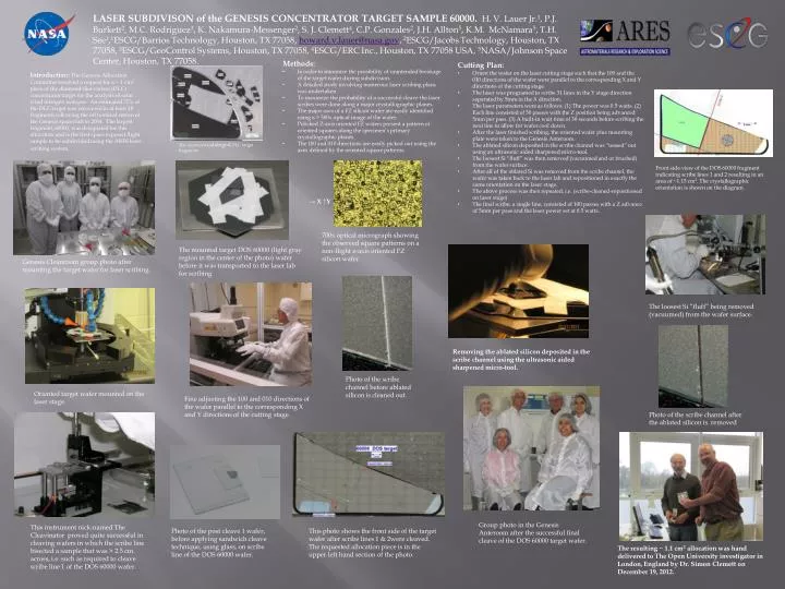
LASER SUBDIVISON of the GENESIS CONCENTRATOR TARGET SAMPLE 60000. H. V. Lauer Jr.1, P.J. Burkett2, M.C. Rodriguez3, K. Nakamura-Messenger2, S. J. Clemett4, C.P. Gonzales2, J.H. Allton5, K.M. McNamara5, T.H. See1,1ESCG/Barrios Technology, Houston, TX 77058, howard.v.lauer@nasa.gov, 2ESCG/Jacobs Technology, Houston, TX 77058, 3ESCG/GeoControlSystems, Houston, TX 77058, 4ESCG/ERC Inc., Houston, TX 77058 USA, 5NASA/Johnson Space Center, Houston, TX 77058. • Methods: • In order to minimize the possibility of unintended breakage of the target wafer during subdivision. • A detailed study involving numerous laser scribing plans was undertaken. • To maximize the probability of a successful cleave the laser scribes were done along a major crystallographic planes. • The major axes of a FZ silicon wafer are easily identified using a > 500x optical image of the wafer. • Polished Z-axis oriented FZ wafers present a pattern of oriented squares along the specimen’s primary crystallographic planes. • The 100 and 010 directions are easily picked out using the axes defined by the oriented square patterns. • Cutting Plan: • Orient the wafer on the laser cutting stage such that the 100 and the 010 directions of the wafer were parallel to the corresponding X and Y directions of the cutting stage. • The laser was programed to scribe 31 lines in the Y stage direction separated by 5mm in the X direction. • The laser parameters were as follows. (1) The power was 0.5 watts. (2) Each line consisted of 50 passes with the Z position being advanced 5mm per pass. (3) A built-in wait time of 30 seconds before scribing the next line to allow for wafer cool down. • After the laser finished scribing, the oriented wafer plus mounting plate were taken to the Genesis Anteroom. • The ablated silicon deposited in the scribe channel was “teased” out using an ultrasonic aided sharpened micro-tool. • The loosest Si “fluff” was then removed (vacuumed and or brushed) from the wafer surface. • After all of the ablated Si was removed from the scribe channel, the wafer was taken back to the laser lab and repositioned in exactly the same orientation on the laser stage. • The above process was then repeated, i.e. (scribe-cleaned-repositioned on laser stage) • The final scribe, a single line, consisted of 100 passes with a Z advance of 5mm per pass and the laser power set at 0.5 watts. Introduction: The Genesis Allocation Committee received a request for a ~ 1 cm2 piece of the diamond-like-carbon (DLC) concentrator target for the analysis of solar wind nitrogen isotopes. An estimated 75% of the DLC target was recovered in at least 18 fragments following the off nominal return of the Genesis spacecraft in 2004. The largest fragment, 60000, was designated for this allocation and is the first space exposed flight sample to be subdivided using the ARES laser scribing system. The recoveredcataloged DLC target fragments. Front side viewof the DOS 60000 fragment indicating scribe lines 1 and 2 resulting in an area of ~1.15 cm2. The crystallographic orientation is shown on the diagram. → X ↑Y 700x optical micrograph showing the observed square patterns on a non-flight z-axis oriented FZ silicon wafer. The mounted target DOS 60000 (light gray region in the center of the photo) wafer before it was transported to the laser lab for scribing Genesis Cleanroom group photo after mounting the target wafer for laser scribing. The loosest Si “fluff” being removed (vacuumed) from the wafer surface. Removing the ablated silicon deposited in the scribe channel using the ultrasonic aided sharpened micro-tool. Photo of the scribe channel before ablated silicon is cleaned out. Oriented target wafer mounted on the laser stage. Fine adjusting the 100 and 010 directions of the wafer parallel to the corresponding X and Y directions of the cutting stage. Photo of the scribe channel after the ablated silicon is. removed Group photo in the Genesis Anteroom after the successful final cleave of the DOS 60000 target wafer. This instrument nick-named The Cleavinatorproved quite successful in cleaving wafers in whichthe scribe line bisected a sample that was > 2.5 cm across, i.e. such as required to cleave scribe line 1 of the DOS 60000 wafer. Photo of the post cleave 1 wafer, before applying sandwich cleave technique, using glass, on scribe line of the DOS 60000 wafer. This photo shows the front side of the target wafer after scribe lines 1 & 2were cleaved. The requested allocation piece is in the upper left hand section of the photo. The resulting ~ 1.1 cm2 allocation was hand delivered to The Open University investigator in London, England by Dr. Simon Clemett on December 19, 2012.