Download
1 / 35
350 likes | 501 Views
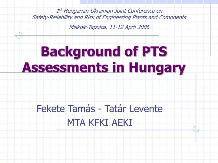
1 st Hungarian-Ukrainian Joint Conference on Safety-Reliability and Risk of Engineering Plants and Compnents Miskolc-Tapolca, 11-12 April 2006. Background of PTS Assessments in Hungary. Fekete Tamás - Tatár Levente MTA KFKI AEKI. reaktorfedél. M140 X 6 csavar (60 db). Leszorító gyűrű.

E N D
1st Hungarian-Ukrainian Joint Conference onSafety-Reliability and Risk of Engineering Plants and Compnents Miskolc-Tapolca, 11-12 April 2006 Background of PTS Assessments in Hungary Fekete Tamás - Tatár Levente MTA KFKI AEKI
reaktorfedél M140X6 csavar (60 db) Leszorító gyűrű 6/8 varrat 8/9 varrat 1/2 varrat 2/3 varrat Csonkzóna 3/5 varrat NA 500 csonk 5/6 varrat Aktív zóna Hengeres öv Elliptikus fenék VVER 440-213installed Reactor Pressure Vessel at Paks NPP
PTS Methodology Development • PTS Methodology Development: • Ageing of structural materials influences applicability of equipments to a great extent. • Longer lifetime is advantageous. • Several factors cause material damage. • Role of material models in PTS calculations. • AEKI works on physical models of materials and structures.
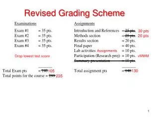
Methodology of PTS Calculations The Hungarian Reg. Guide No. 3.17 Status of PTS calculations: Fluence Calculations (material ageing) TH Calculations (thermal boundary conditions) Integrity Calculations Material Data Flow curves Fracture mechanics data
Status of PTS Calculations I. • Fluence Calculations:Realistic 3D fluence calculations for re-evaluation of surveillance data and for lifetime calculations
Status of PTS Calculations II. • System Thermal-Hydraulics:System Codes:Relap5 /Mod3.3 AthletStratification/ local mixing calculations:REMIX • Structural Integrity Calculations:Computer Code:MSC.MARC2005r2
System Nodalisation for TH Calculations 6 loop model of the Primary Circuit has been applied
RPV Nodalisation for TH Calculations 6 loop TH model
Selected TH transients for Calculations I. A total number of ≈40 cases (including subcases) Shut-down cases: Steam line break (SYSTEM) Inadvertent opening of pressuriser safety valve (SYSTEM+local mixing) Power level: 100% and 108% nominal power Steam line break (SYSTEM) Inadvertent operation of HPIS (SYSTEM) Inadvertent opening of pressuriser safety valve (SYSTEM+local mixing) Steam generator collector cover opening (SYSTEM)
Selected TH transients for Calculations II. • Loss of coolant accidents: • Ø73 mm make-up line (SYSTEM+local mixing) • Ø90 mm Pressuriser spray line (SYSTEM+local mixing) • Ø111 mm HPIS line (SYSTEM+local mixing) • Ø233 mm LPIS line (SYSTEM+local mixing) • Ø492 mm cold leg single ended break (SYSTEM) • Ø492 mm cold leg double ended break (SYSTEM) • Ø492 mm hot leg double ended break (SYSTEM)
Cold leg model for structural integrity calculations Variations of Temperature and HTC in cold leg are considered Interactions between cold legs are considered
Temperature and pressure variation in the downcomer during a Ø233 mm LPIS line break event
Temperature and pressure variation in the downcomer during a LBLOCA event
Temperature and pressure variation in the downcomer during a Steam Line Break event
Results of thermohydraulical analysis = Result of computation ‘Simplified’ computation ‘3 D’ computation RPV geometry Thermal boundary conditions from thermohydraulic data Thermal boundary conditions from thermohydraulic data ? Thermo-physical properties of RPV materials Thermal field determination in RPV wall Thermal field determination in RPV wall Thermal computation ? Displacement, deformation and stress field determination in RPV wall Elasto-plastic properties of RPV materials Mechanical boundary conditions Stress field determination in RPV wall Deformation and stress field computation ? Distribution of fracture mechanical material properties in RPV wall Fracture mechanics properties of RPV materials General data characterising RPV material ageing Distribution of fracture mechanical material properties in RPV wall ? Determination of loading on postulated cracks Determination of loading on postulated cracks Fracture mechanics computation Geometry of postulated cracks ? Crack stability analysis, crack propagation Crack stability analysis, crack propagation ? RPV integrity criteria RPV integrity assessment RPV integrity assessment • Two-level methodology of PTS calculations • Simplified models and calculations(conservative) • Realistic models andcalculations
1. Simplified models and calculations • Conservative calculations on simplified models • Cylindrical part of the RPV is modelled • Linear-elastic stress-deformation calculations (small deformation-small displacement) • Cladding is taken into account • Residual stresses in welds are considered • Defect locations: welds, core middle • Spectrum of postulated, semielliptical cracks (a/c = 1/3, a = 1 [mm] – 0,25s, through clad) • Simplified LEFM calculations (analytical formulas) • WPS effect is taken into account (tangent, 90%) • Crack arrest calculations for some transients Main goal of the calculations: selection of most severe transients
2. Realistic models and calculations • Realistic calculations on the whole RPV body • The whole RPV is modelled • Elastic-plastic stress-deformation calculations (large deformation – large displacement) • Cladding is taken into account • Residual stresses in welds are considered • Defect locations: welds, core middle, nozzle etc. • 1 postulated crack /location (a/c = 1/3, underclad) • EPFM calculations on defects in FE mesh • KIfrom J integral • WPS effect is taken into account (tangent, 90%) • Crack arrest calculations for some transients Goal: Assessment of life-time
Computer Codes used for calculations • For structural integrity calculations te MSC.MARC2005r2 code is used • Nonlinear capabilities of MSC.Marc – large deformations – material nonlinearities • Global-local option can be used to make calculations on subcomponents easily • Coupled termal-mechanical problems can be calculated • Auxiliary codes are used to generate boundary conditions from TH data to structural integrity calculations
Geometrical Models of the RPV 1.)3D model of Beltline Region 2.)3D model of Beltline Regionwith elliptic bottom 3.)3D model of Ø492 nozzles 4.)3D model of Ø260 nozzles 5.)Global 3D Model of a VVER 440-V213 RPV 6.)3D Flaw Model 7.) 3D Model of the Upper Part All Models are Modular, Parametric and Material Independent
Influence of cladding on stress calculations(conservative realistic material behaviour) Embrittlement of cladding can have very strong influence on results of integrity calculations. That effect is proportional with the age of a RPV. Parametric study, various aged state of the cladding: – not irradiated – irradiated ( EOL/4) – irradiated ( EOL) Transient: LBLOCA
Temperature distribution in pressure vessel wall at 100th [s].
t, KI distribution in pressure vessel wall at 100th [s].Unirradiated state of cladding
t, KI distribution in pressure vessel wall at 100th [s].Irradiated cladding ( EOL/4)
t, KI distribution in pressure vessel wall at 100th [s].Irradiated cladding ( EOL)