Download
1 / 33
330 likes | 634 Views
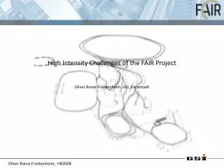
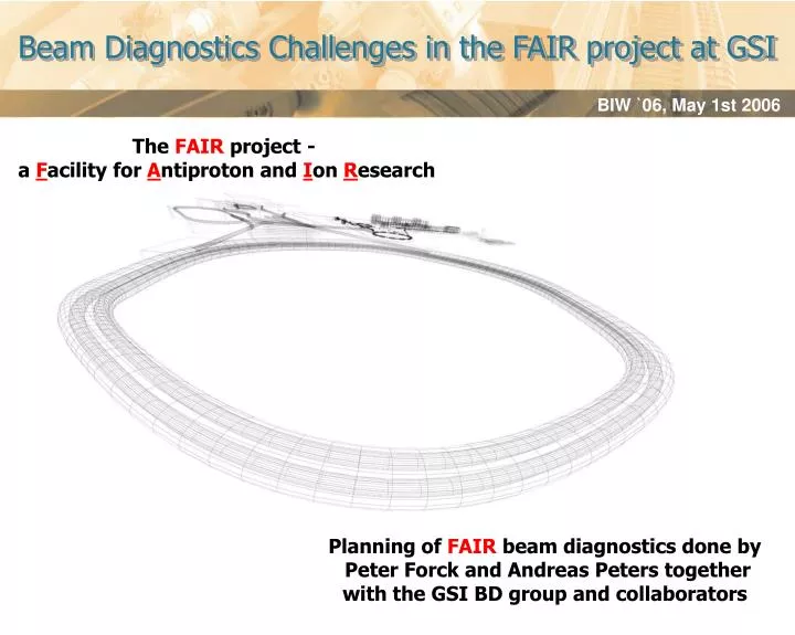
Beam Diagnostics Challenges in the FAIR project at GSI. The FAIR project - a F acility for A ntiproton and I on R esearch. Planning of FAIR beam diagnostics done by Peter Forck and Andreas Peters together with the GSI BD group and collaborators . Outline.

E N D
Beam Diagnostics Challenges in the FAIR project at GSI The FAIR project - a Facility for Antiproton and Ion Research Planning of FAIR beam diagnostics done by Peter Forck and Andreas Peters together with the GSI BD group and collaborators
Outline • The FAIR project – a short introduction to the accelerator parameters and the facility layout and operation modes as well as the research aims • Challenges in the accelerator parameters • Linked general challenges for the beam diagnostic equipment (diversity and dynamics) • Examples of beam diagnostic challenges in detail and R&D for possible solutions: • Current measurement in SIS100 from dc to short single bunch operation • BPM systems for the cryogenic synchrotrons with varying acceleration frequencies • Turn-by-turn profile measurement (RGM) in synchrotrons and storage rings with high repetition rates (MHz) under UHV conditions • Summary and outlook Beam Diagnostic Challenges in the FAIR Project
Today Future Project Beams in the future: Intensity:100 – 1000 fold Species: Z =-1– 92 (anti-protons to uranium) Energies:up to 35 - 45 GeV/u Precision:full beam cooling 100 m FAIR – Basic Layout and Parameters (1) Beams now: Z = 1 – 92 (protons to uranium) up to 2 GeV/nucleon Some beam cooling Beam Diagnostic Challenges in the FAIR Project
FAIR – Basic Layout and Parameters (2) Final facility layout with all planned buildings Tunnel for SIS100/300 at a depth of about 17m to comply with the requirements of radiation safety Beam Diagnostic Challenges in the FAIR Project
Booster synchrotron SIS18: 2.7·1011 U28+-ions, 2.7 Hz 5.4·1012 protons, 4 Hz Main synchrotrons of FAIR: SIS100, 2T, pulsed sc. magnets, 29 GeV, 4·1013 protons, 25 ns 2.7 GeV/u, 1012 U28+-ions, 60 ns SIS300, 6T, pulsed sc. magnets, 34 GeV/u, 4·1011 U92+-ions, slow extraction (1 – 100 s) UNILAC (upgraded): 15 emA U28+, 11.4 Mev/u 100 m FAIR – Basic Layout and Parameters (3) p-Linac (new): 70 mA, 70 MeV Injector chain Beam Diagnostic Challenges in the FAIR Project
Targets and storage rings of FAIR: SFRS Target CR: stochastic cooling of RIBs, and antiprotons, mass spectr. RESR: accumulation of anti- protons, fast decel. of RIBs NESR: e-cooling of RIBs and and antiprotons, precise mass spectr., e-n scattering facility Antiproton Target HESR: stoch. cooling up to 14 GeV antiprotons, e-cooling up to 9 GeV, internal target 100 m FAIR – Basic Layout and Parameters (4) Beam Diagnostic Challenges in the FAIR Project
Scheme of FAIR Parallel Operation Beam Diagnostic Challenges in the FAIR Project
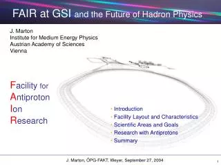
Nuclear Structure & Astrophysics withradioactive beams Plasma Physics with compressed ion beams & high- intensity petawatt- laser Hadron Physics with antiprotons 100 m Research Areas at FAIR Nuclear Matter Physics with 35-45 GeV/u HI beams High EM Field (HI) --- Fundamental Studies(HI & p) Applications (HI) Beam Diagnostic Challenges in the FAIR Project
Challenges in the Accelerator Parameters (1) • Fast cycling superconducting magnets: For SIS 100 superconducting magnets (2 T) with 4 T/s ramping rate are required. SIS 300 will be equipped with 6 T (1 T/s) dipole magnets. The optimization of the magnet field quality for low loss, high current operation with beams filling large parts of the acceptance is of great importance. • Control of the dynamic vacuum pressurecaused by beam loss induced desorption of heavy molecules, which can cause the rapid increase of the residual gas pressure a novel collimation concept is presently under test at the SIS18. • Cooled secondary beams: Fast electron and stochastic cooling at medium and at high energies will be essential for experiments with exotic ions and with antiprotons. • High RF voltage gradients: The fast acceleration and bunch compression of intense heavy-ion beams down to ~60 nanosecond bunch length (protons: ~25 ns) requires compact RF systems. Complex RF manipulations with minimum phase space dilution and the reduction of the total beam loading in the RF systems are important R&D issues. • Operation with high brightness, high current beams: The synchrotrons will operate close to the space charge limits with tolerable beam losses of the order of a few percent. The control of collective instabilities and the reduction of the ring impedances is a subject for the R&D phase. Beam Diagnostic Challenges in the FAIR Project
Challenges in the Accelerator Parameters (2) Cross section of the synchrotron tunnel with an inner size of 5 x 4 m2, SIS100 (bottom) and SIS300 (top) cryostats are shown with cryogenic bypass lines (yellow) Straight section of the synchrotron tunnel with a shielded small recess building Beam Diagnostic Challenges in the FAIR Project
General Challenges for Beam Diagnostics (1) • Despite quite different beam parameters of the FAIR synchrotrons and storage rings, common realizations of SIS100, SIS300 and all storage ring diagnostics are mandatory to save man-power and costs during the R&D phase and enable a cost reduction due to the large quantities during the construction phase. • Large dynamic range, e.g. in SIS100: from low currents beams for adjustments up to space charge limited intensities of heavy ions, from long bunches at injections up to short pulses after bunch rotation / compression. • Because the acceptance was limited to 3*emittance (KV-Distribution) in the synchrotrons and 2*emittance in the transfer lines , a precise alignment of the beam in the vacuum pipe is strongly advised. The beam diagnostics system has to allow a precise orbit measurement and the capability for online feedback on the closed orbit, on the betatron tune, on chromaticity and on coupling. • If the loss budget in the superconducting synchrotrons is only a few percent, current measurements with high accuracy (~10-4) for controlling beam losses are mandatory. Beam Diagnostic Challenges in the FAIR Project
General Challenges for Beam Diagnostics (2) • Due to the compactness of all accelerators the repetition rates are quite high (up to the MHz region), which is a challenging task e.g. for turn-by-turn profile measurements based on a RGM system. • Additional constraints have to be fulfilled, which are sometimes challenging: • installations in cryogenic parts of the accelerators, • UHV conditions (pressure: 5×10-12 mbar) and • high radiation levels. • The complex, „quasi-parallel“ operation scheme demands a highly reliable and flexible data acquisition system adapted to the fast pulsed machines parameters. • Complicated scheme of transport lines with high diversity of magnetic rigidities. Beam Diagnostic Challenges in the FAIR Project
General Challenges for Beam Diagnostics (3) • Schematic view of FAIR beam transport lines • Total length of about 2350m of allbeam lines (excluding Antiproton-Separator, FLAIR beam lines, ...), divided in 46 sections with differing parameters. • In the transfer lines the high dynamic range of intensities and energies as well as ion species leads to the necessity of destructive measurement methods needed for low currents and in parallel to non-destructive devices for high currents which would destroy any material in the beam optical path. Beam Diagnostic Challenges in the FAIR Project
Beam Diagnostic Challenges in Detail • Examples of beam diagnostic challenges concerning the ring accelerators in detail and R&D for possible solutions: • Current measurement in SIS100 from dc to short single bunch operation (operating bandwidth of 10 kHz) • BPM systems for the cryogenic synchrotron environment with varying acceleration frequencies • Turn-by-turn profile measurement (RGM) in synchrotrons and storage rings with high repetition rates (MHz) under UHV conditions Beam Diagnostic Challenges in the FAIR Project
Current Measurement in SIS100 (a) Theoretical upper limits of currents in SIS100 Beam Diagnostic Challenges in the FAIR Project
Current Measurement in SIS100 (b) Solutions: a) Use the NPCT of Bergoz; an installation in SIS18 is scheduled for August 2006 and tests starting in October 2006 – Question: Will the feedback loop of the NPCT work stable under high current bunched beam condition (bunch frequency of some MHz) ? Severe problem of GSI DCCT: Above specific levels of beam current and/or revolution frequency the loop starts to oscillate (right). Mostly it gets back control. But: Did it settle to the correct working point ? Beam Diagnostic Challenges in the FAIR Project
Current Measurement in SIS100 (c) Solutions: b) Design of an alternative current measurement based on the idea of a clip-on ampere-meter with a GMR sensor in the gap of a toroidal core (collaboration with University of Kassel, Germany). Scheme of an clip-on ampere-meter Simulated magnetic flux in a slit toroidal core Beam Diagnostic Challenges in the FAIR Project
Current Measurement in SIS100 (d) Assuming a measurement bandwidth of 10 kHz, the resolution of different GMR sensors is in the order of ~100 nT Resolution measurement of different GMR sensors (by NVE corporation) Beam Diagnostic Challenges in the FAIR Project
Current Measurement in SIS100 (e) Example for the DC characteristics of a GMR sensor (NVE AA005) Data sheet characteristics: Saturation field: 10 mT Specified linear range:± 0 – 7 mT Operating frequency: dc 1 MHz Measurements concerning high frequency behaviour are under way ! Beam Diagnostic Challenges in the FAIR Project
Current Measurement in SIS100 (f) Construction of a first test set-up with a split core (either VITROVAC 6025 F or CMD 5005 from CMI ferrite) and two gaps for sensor positioning to be built in SIS18 in autumn 2006 Details Existing SIS18 DCCT with added new core Due to the two half shells an installation without vacuum break is possible! Beam Diagnostic Challenges in the FAIR Project
BPM development - detector (a) Curved section of SIS100 Straight section of SIS100 Beam Diagnostic Challenges in the FAIR Project
Apertures/mm: horizontal = 268 vertical = 116 length = 350 simulated beam separation rings on the ground potential BPM development – detector (b) Starting point: ESR BPM • Different types of BPMs are necessary: • SIS100 version: elliptical, cryogenic • SIS300 version: round, cryogenic • Storage rings: large aperture up to 300 mm, normal temperature env., but high bakeout temperatures Position sensitivity and linearity: For shoe-box type calculated Δx(f) = K(f) * Δ/Σ+ offset(f) Careful mechanical design (high f by bunch-compression) R&D: Matching RF- andcyrogenic requirements Necessity of guard rings (1) Beam Diagnostic Challenges in the FAIR Project
BPM development – detector (c) • Necessity of guard rings (2) • Cross talk between plates in one plane (should be low!) Simulations on ESR type: separation rings on the ground potential • Metal plates seem to be the better choice, but: • Mechanical stability of an arrangement of numerous single metal plates is poor due to experience from collaborators in Dubna (Nuclotron)! • Structure on ceramics chosen! Beam Diagnostic Challenges in the FAIR Project
BPM development – detector (d) For maximal beam current i.e. Nz 4x10¹³ e/bunch and bunch length of 25 ns: Qm=4.3 x 10⁻⁷ C U=4.3 kV Present layout of SIS100 BPM version (elliptical shape) For minimal beam current i.e. Nz 4x10⁸ e/bunch and bunch length of 60 ns: Qm=4.4 x 10⁻¹³ C U=4.4 mV BPM parameters: Capacity: ~ 100 pF Length: 30 cm Barrier bucket behaviour (long bunches!) not studied until now! Further adjustment of parameters needed! Beam Diagnostic Challenges in the FAIR Project
BPM development – analog electronics (e) (from CERN-PS) J. Belleman From CS In the case of SIS100/300 the hybrid must most likely positioned in the cryogenic area! Beam Diagnostic Challenges in the FAIR Project
BPM – data acquisition and analysis (f) Behind the amplifier chain no additional analog signal treating direct digitization! Common EU-FP6-initiative of GSI, CERN and Instrumentation Technologies for a digital data evaluation platform for fast cycling hadron machines with varying frequencies: Scheme of Libera electronics Main board 4 channel ADC input board Beam Diagnostic Challenges in the FAIR Project
Libera PU signal Position calculation outside the FPGA due to floating point limitation Summing of each data sample at the input -> gate construction using the fact that the data between 2 bunches should have a linear trend Integration over each bunch using the constructed gates ADC Averaging for noise reduction, using a median filter with a short length of 5 taps SBC FPGA BPM development – data acquisition and analysis (g) • Two different approaches for data evaluation are under development now: • CERN: digital version of classical base line restoring and PLL implementation using RF frequency input and phase tables • GSI: Free running algorithm with the following implementation: Beam Diagnostic Challenges in the FAIR Project
BPM development – data acquisition and analysis (h) Results of offline implementation/calculation: Measurement in SIS18 harmonic number = 4 Both methods (CERN/GSI) are under development and implementation in FPGA code; test are foreseen in the 2nd half of 2006 ! Beam Diagnostic Challenges in the FAIR Project
RGMDevelopment – Requirements (a) • Parameters given by the machines: • Revolution frequency • in SIS 100/300: 110 – 280 kHz • in the Storage Rings: 125 kHz – 1.4 MHz • Beam pipe apertures: • in SIS 100/300: 135 * 65 mm2, resp. 90 mm in diameter (SIS300) • in the Storage Rings: up to 300 mm in diameter • adaptive spatial resolution down to 0.1 mm (rel. 1%) necessary due to cooled beams • Transversal measurement range: ~ 100 mm • Turn-by-turn readout necessary e.g. for matching of the injected beam emittance orientation and dispersion setting with respect to the acceptance • Detection of secondary e-/ions ( conversion with e.g. phosphor P47) , thus • E-field (E50 V/mm, 1% in-homogeneity) and • B-field for guidance (B0.03 T, 1% in-homogeneity) compact because of limited space • Read-Out Modes: a) high resolution measurement on ms time scale with CCD camera • b) turn-by-turn: array of ~100 photo-diodes or multi-anode PM or SiPM Beam Diagnostic Challenges in the FAIR Project
RGM development – mechanical design (b) • First design of RGM with magnets, but the following changes are necessary: • Possibility of change between CCD and multi-diode readout • Due to low magnetic rigidities in the storage rings compensations of the applied magnetic fields of the RGM are necessary more complex magnet installations • Alternative design with permanent magnets is under calculation at ITEP, Moscow First test of RGM version with CCD readout, but without magnetic field are foreseen in collaboration with FZ Jülich at their COSY proton storage ring in the 2nd half of 2006! Beam Diagnostic Challenges in the FAIR Project
RGM development – turn-by-turn readout (c) Alternative sensor for turn-by-turn readout: Silicon Photomultiplier (B. DOLGOSHEIN et al., MEPI, Moscow) First commercial sensor on the market (www.SensL.com) Up to 103 silicon micro pixels permm2, dimensions scalable Beam Diagnostic Challenges in the FAIR Project
The Most Challenging Part of the FAIR Project ... Realisation/Stage Plan 2007 (start of final design) 2014 Stage 1 Stage 2 Stage 3 Beam Diagnostic Challenges in the FAIR Project
Acknowledgement Instead of a summary: Thanks to all colleagues and collaborators contributing to this talk with their papers and pictures! Thanks to our small technical review board (Tom Shea and Hermann Schmickler) for valuable discussion and their consulting! Thanks for your attention! Beam Diagnostic Challenges in the FAIR Project