Download
1 / 16
160 likes | 272 Views
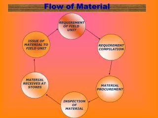
09-17-08 Nature of friction in extrusion process and its effect on material flow Josh Hawks. Flitta and T. Sheppard 2003 IoM Communications Ltd. Published by Maney for the Institute of Materials, Minerals and Mining. Function of Article.

E N D
09-17-08Nature of friction in extrusion process and itseffect on material flowJosh Hawks Flitta and T. Sheppard 2003 IoM Communications Ltd. Published by Maney for the Institute of Materials, Minerals and Mining.
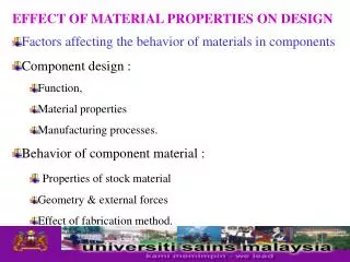
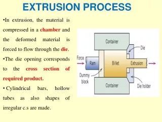
Function of Article • To describe the simulation of the extrusion process and in particular the effect of the initial billet temperature on friction and its consequences on material flow. • To compare the numerical simulation and experimental results for the effect of initial billet temperature on the deformation zone pattern and its consequent effect on friction.
Why is this information important? • The results show that the friction factor between billet and container wall varies with billet temperature • With the increasing use of finite element method (FEM) techniques to the extrusion process, the necessity for accurate input data becomes important for research
1. t. sheppard: ‘Extrusion of aluminium alloys’; 1999, Dordrecht, Kluwer Academic Press. 2. i. flitta and t. sheppard: Proc. 7th Int. Seminar on ‘Aluminium extrusion technology’, Chicago, 197 – 203; 2000, Washington, DC, The Aluminium Association. 3. i. flitta and t. sheppard: Proc. 5th Int. ESAFORM Conf., Krakow, Poland, April 2002, European Scienti. c Association for Material Forming, 435 – 438. 4. t. chanda, j. zhou, l. kowalsi and j. duszczyk: Sci. Mater., 1999, 41, 195 – 202. 5. b. j. e. van rens, w. a. m. brelemans and f. p. t. baajens: Proc. 7th Int. Seminar on ‘Aluminium extrusion technology’, Chicago, 99 – 107; 2000, Washington, DC, The Aluminium Association. 6. t. a. dean and z. m. hu: Proc. 6th Int. Conf. on ‘Technology of plasticity’, Nuremburg, Germany, September 1999, Vol. 1, 541 – 550; Springer – Verlag. 7. s. abtahi, t. welo and s. storen: Proc. 6th Int. Seminar on ‘Aluminium extrusion technology’, Chicago, 125 – 131; 1996, Washington, DC, The Aluminium Association. 8. t. welo, t. s. abtahi and i. skauvik: Proc. 6th Int. Seminar on ‘Aluminium extrusion technology’, Chicago, 101 – 106; 1996, Washington, DC, The Aluminium Association. 9. l. anand: Comput. Mech., 1993, 12, 197 – 213. 10. l. anand and w. tong: Ann. CIRP, 1993, 42, 361 – 366. 11. m. p. clode and t. sheppard: Mater. Sci. Technol., 1990, 6, 755 – 763. 12. t. chanda, j. zhou, l. kowalsi and j. duszczyk: Proc. 7th Int. Seminar on ‘Aluminium extrusion technology’, Chicago, 125 – 134; 2000, Washington, DC, The Aluminium association. 13. r. j. dashwood and h. b. mcshane: Proc. 6th Int. Seminar on ‘Aluminium extrusion technology’, Chicago, 331 – 339; 1996, Washington, DC, The Aluminium Association. 14. a. heege, p. alart and e. onate: Eng. Comput., 1995, 12, 41 – 656. 15. d. y. yang: Ann. CIRP, 1994, 43, 229– 233. 16. j. subramaniyan: PhD Thesis, Imperial College, London, 1989. 17. r. p. vierod: PhD Thesis, Imperial College, London, 1983. 18. t. sheppard and s. j. j. patterson: Mech. Work. Technol., 1982, 4, 39 – 56. 19. j.-l. chenot et al.: Int. Conf. on ‘Forging and related technology’ (ICFT 98), 113 – 122; 1998, Suffolk, Professional Engineering. 20. ‘Software manual,’ FORGE3 Version 5.3 Transvalor SA, Sophia Antipolis, France, 2001. 21. c. m. sellars and d. tegart: Int. Met. Rev., 1972, 1, 17. 22. t. sheppard and d. wright: Met. Technol., 1979, 13, 215 – 223. 23. m. g. tutcher: PhD Thesis, Imperial College, London, 1979. References
L Do p Df How It Relates to ME EN 482 Extrusion Model • Assumptions: • Circular cross-section • Uniform stress distribution p = ram pressure L = remaining billet lengthDo = chamber diameter Df = extrudate diameter
Define extrusion ratio = rx = Ao/Af Frictionless model: ideal true strain = e = ln rx ideal ram pressure = p = Yf ln rx With friction: Johnson eqn ex = a + b ln rx How It Relates to ME EN 482 Cont. Extrusion Model – stress and strain Ao = billet (chamber) area Af = extrudate area a = 0.81.2 £ b £ 1.5
Parameters and Design • tF is the interfacial friction • tmax is the shear yield stress of the billet material. • δ¯ is the mean equivalent yield stress, • δ ¯ /√ 3 is the mean equivalent shear flow stress • m¯ is the factor of proportionality and is commonly referred to as a friction factor and varies between m¯~0 for perfect lubrication and m¯~1 for sticking friction • r is the density • c the specific heat • T is the temperature • Q is the internal heat dissipation generated by plastic deformation • k is the conductivity • Z is termed the temperature compensated strain rate (s21 ); • DH is the activation energy for deformation (kJ mol21) • G is the universal gas constant (8.314 J mol21 K21 ) • e¯ is the mean equivalent strain rate (s21 ); • A(s21 ) and n are constants • a is a constant (m2 MN21 ) • T is the initial billet temperature (K)
Parameters and Design Cont. At the extreme condition between the billet and the container, friction at the interface cannot exceed the shear strength of the material. This extreme condition is termed sticking friction and can be represented generally as tF~tmax A modification to sticking friction is often introduced to account for the fact that friction forces are seldom as high as the shear strength of a material The most widely used equation to describe the deformation of aluminium alloys, is that proposed by Sellars and Tegart and subsequently modified by Sheppard and Wright to yield the steady state flow stress from the equation
Experimental Design cont. From which we can derive Input Properties for Simulation
Parameters and Design Cont. Temperatures in the Billet and the die were computed using
Experimental Design Experiments were performed on a 5 MN (560 Ton) press vertically mounted with a heated container. The main ram was driven by a hydraulic pump during the extrusion cycle. The load was measured by Mayes load cell situated directly above the ram, the output from the cell being recorded on a Labmaster data recorder. Ram displacement and speeds were measured by a rectilinear potentiometer fixed between the moving crossheads and the press bolster
Industrial Use • Models can be used to predict the “minimum discard” (material not extruded) • Useful for FEM modeling, materials science research, etc • Since current modeling and estimates are good enough to give “ball park” values and since safety factors are used in design, there is little real practical industrial use.
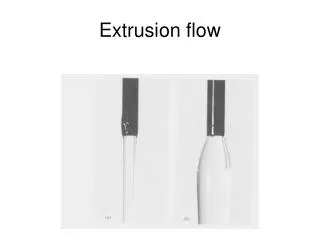
Technical Advancement • Study showed that an increase in Billet temperature resulted in increased “dead metal” zone and increased friction factor (A) dead metal zone; (B) surface generation zone; (C) main deformation zone; (D) central deformation zone 13 Flow velocity of material during extrusion at 450°C
Industries Affected • Aluminum extrusion industry • Other industries not listed in Article