Download
1 / 15
150 likes | 296 Views
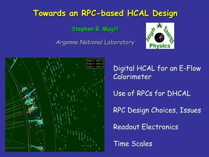
Towards an RPC-based HCAL Design. Stephen R. Magill Argonne National Laboratory. Digital HCAL for an E-Flow Calorimeter Use of RPCs for DHCAL RPC Design Choices, Issues Readout Electronics Time Scales. Summary of Recent Mini-Workshop on RPCs for a LC HCAL.

E N D
Towards an RPC-based HCAL Design Stephen R. Magill Argonne National Laboratory Digital HCAL for an E-Flow Calorimeter Use of RPCs for DHCAL RPC Design Choices, Issues Readout Electronics Time Scales
Summary of Recent Mini-Workshop on RPCs for a LC HCAL Organized by J. Repond at ANL – November 1 Participants : G. Drake, V. Guarino, S. Kuhlmann, S. Magill, B. Musgrave, J. Repond, D. Underwood, B. Wicklund Argonne National Laboratory J. Butler, M. Narain Boston University E. Blucher, M. Oreglia University of Chicago Topics : RPC Parameters Design Choices/Optimizations Issues/Concerns for R&D Mechanical/Electronics R&D Time Scales
Digital HCAL for an E-Flow Calorimeter W,Z 75%/M 30%/M • Can explore EWSB thru the interactions : • e+e- -> WW and e+e- -> ZZ • -> Requires Z,W ID from dijets • -> Can’t use (traditional) constrained fits Charged particles ~ 62% of jet energy -> Tracker/pT ~ 5 X 10⁻⁵ pT 190 MeV energy resolution to 100 GeV Jet Photons ~ 25% of jet energy -> ECAL/E ~ 15-20%/E : ~900 MeV to energy resolution Neutral Hadrons ~ 13% of jet energy -> HCAL<3 GeV to resolution -> /E < 80%/E
KL0 Analysis – Analog Readout Eaverage ~ 13 GeV /mean ~ 26% Compare to digital
KL0 Analysis - Digital Readout Analog EM + Digital HAD x calibration /mean ~ 24% Slope = 23 hits/GeV Digital Analog Average : ~43 MeV/hit
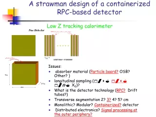
Resistive Plates: Glass or Bakelite Pick-up pad(s) Mylar HV Gas Graphite Use of RPCs for Digital HCAL Generic design • Advantages:Thin layer (≤ 10 mm) • High single particle efficiencies (> 95%) • Flexible geometrical design • Flexible pad readout segmentation • Printed circuit • Simple Front-End readout • Reliable • Underlying physics mostly understood • see http://www.coimbra.lip.pt/~rpc2001/talks.html • Cheap
Design Choices Resistive plates Glass cheap, simple Bakelite needs to be coated with linseed oil source of major problem with BaBar chambers Preferred Geometry Glass thickness Several thicknesses on hand Gas gap thickness Smaller → reduced HV Multiple gaps Smaller gaps → improved long-term stability Higher efficiency Completely different design Preferred Particle HARP Experiment at CERN: TOF
Operation Avalanche mode Faster (~10kHz) Lower HV Smaller signal (~1pC) Needs pre-amplifier Better long-term prognosis No multiple streamers Streamer mode Slower (~1kHz) Higher HV Large signals (~100pC) Sharp signal Multiple streamers Preferred Cosmic ray tests at ANL Charge [pC] Charge [pC] Gas Mixture Freon/Argon/IsoButane 62:30:8 Used by Belle (does not suppress streamers) Freon/IsoButane/SulfurHexafluoride 90:5:5 Used by HARP (suppresses streamers) Many more… High Voltage [kV]
Issues and Concerns Pad structure Safety with HV Using up to 10kV Can be reduced with smaller gaps by operation in avalanche mode Cross talk between pads Significant charge on neighboring pad Reduced with higher resistivity graphite layer 40kΩ/□ → 200kΩ/□ → 1MΩ/ٱ pad – ground plane distance dependence Signal shape very different Easy to discriminate: cross talk at 1- 4% level Long term operation Significant experience elsewhere (L3) Reason for choosing avalanche mode/multiple gaps Overall Thickness Most likely will need 10 mm Calibration Will be needed?
Rate Estimations Recharging time of RPCs : Avalanche mode ~104 Hz Streamer mode ~103 Hz Assume LLC = 0.5x1034 cm-2s-1 = 0.5x10⁻² pb-1s-1 σ1γ(500 GeV) = 4 pb → N/s = 0.02 σ2γ→ee(800 GeV) = 34 mb → N/s = 170x106 σ2γ→μμ(800 GeV) = 473 nb → N/s = 2400 σ2γ→h(800 GeV) = 189 nb → N/s = 945 Easy From V M Budnev et al. Phys. Lett. 15(1974) 181-282 Not our problem Should be ok Particle rates from PYTHIA Beam pipe 24.1 % <E> = 15.7 GeV Endcaps 75.8 % <E> = 1.53 GeV Rate/endcap = 613 Hz 283 Hz (E> 1GeV) Barrel 0.06 % <E> = 5.0 GeV
A Readout Electronics System for RPCs • General Concepts • Each Channel has a Discriminator • – a 1-Bit ADC • Timestamp Each Hit • Store Timestamps in Local Buffers, • Read Out Periodically • No Trigger System • Read Out Timestamps into Trigger Processor • Use Timestamps to Construct Hits • Works Well for Low Event Rates and Low Noise Rates • Like MINOS DAQ
Custom Front-End IC Essential Functions : Low-Noise Preamp (Needed for Avalanche Mode) Discriminator Timestamp Circuitry Holding Buffer Readout • For Testbeam (~400K Channels) – • Will Probably Need Dedicated Run (~$100K, 3-6 Months, Packaging, Wafer Testing...) • Like CDF SVX Detector! • For Production (~50M Channels) – • Cost of Custom IC Design & Fab Will Be Worth It • << $1 /Channel for Chip
Front-End PCB Design Top View – highly-integrated approach Cross-sectional view of multi-layer PCB
Back-End Readout • Essential Functions : • Receive Serial Data Streams • from Front Ends • Concentrate Data • Form "Time Frames“ • (~1 Sec for MINOS) • Send Data to Trigger Processor • Realization : • Use VME Crates for Infrastructure • Data Concentrators Receive Serial data streams from Front Ends • Data Concentrators Also Provide Clock & Control
Time Scales R&D Next 6 months Build chambers: explore different designs R&D with resistive layer Initiate design of prototype chambers Design and build readout pads (multilayer boards) Design and build readout system for O(100 channels) Design custom readout chip Evaluate various designs with respect to : Efficiency Noise rate Rate capability? Cross-talk Prototype Until September of 2004 Finalize prototype design Construct 40 layers of 1m2 corresponding to an 1 m3 HCAL section Build gas mixing/distribution system Select/purchase HV/LV power supplies Evaluate in CERN test beam : Viability of design Validation of MC Comparison with analog HCAL