Download
1 / 17
230 likes | 662 Views
LINTON UNIVERSITY COLLEGE SCHOOL OF CIVIL ENGINEERING. GEO-MECHANICS (CE2204). Soil Stress and Pore Water Pressure. Lecture Week No 2 Mdm Nur Syazwani Noor Rodi. TOTAL VERTICAL STRESS.

E N D
LINTON UNIVERSITY COLLEGE SCHOOL OF CIVIL ENGINEERING GEO-MECHANICS(CE2204) Soil Stress and Pore Water Pressure Lecture Week No 2 MdmNurSyazwani Noor Rodi
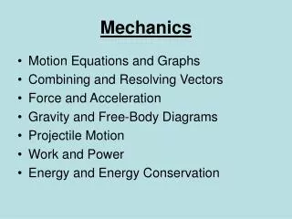
TOTAL VERTICAL STRESS • The total vertical stress (σv)acting at a point below the ground surface is due to the weight of everythinglying above i.e. soil, water, and surface loading • Total vertical stresses are calculated from the unit weight of the soil • Any change in total vertical stress (σv) may also result in a change in the horizontal total stress (σ h) at the same point • The relationships between vertical and horizontal stress are complex (Δσv ≠ Δσh)
TOTAL VERTICAL STRESS in homogeneous soil σv σv Ground Level SOIL ELEMENT Depth, z
TOTAL VERTICAL STRESS below a river or lake zw Ground Level Water Level z
TOTAL VERTICAL STRESS in multi-layered soil Ground Level z1 Soil1 z2 Soil2 z3 Soil3
TOTAL VERTICAL STRESS with a surface surcharge load Very ‘wide’ surcharge, q (kN/m2) Ground Level z
PORE WATER PRESSURE • The water in the pores of a soil is called pore water. • The pressure within this porewater is called pore water pressure (u) • The magnitude of pore water pressure depends on: • the depth below the water table • the conditions of seepage flow
PORE WATER PRESSUREunder hydrostatic conditions (no water flow) Ground Level Water Table z
EFFECTIVE STRESS CONCEPT(Terzaghi, 1923) where = Total Vertical Stress = Effective Stress = Pore Water Pressure
VERTICAL EFFECTIVE STRESSES Water Table Ground Level z
EXAMPLE 1 Plot the variation of total and effective vertical stresses, and pore water pressure with depth for the soil profile shown below Ground Level kN/m3 Water Table GRAVELY SAND 4m kN/m3 2m 4m SAND kN/m3 5m SAND GRAVEL kN/m3
EXAMPLE 2 The soil layers on a site consists of: 0 – 4 m Gravel-sand (ρsat= 2038 kg/m3; ρB 1957 kg/m3) 4 – 9 m Clay (ρsat= 1835 kg/m3) Draw an effective stress and total stress profile between 0 – 9m, when the water table is 1m above the top of the clay
EXAMPLE 3 • On a certain site a surface layer of silty sand is 4m thick and overlies a layer of peaty clay 7m thick, which in turn is underlain by impermeable rock. Draw effective and total stress profiles for the following condition: • Water table at the surface • Water table at a depth of 5m, with the silty sand above the water table saturated with capillary water • Unit weight: • Silty Sand = 18.5 kN/m3 • Clay = 17.7 kN/m3
EXAMPLE 4 • A confined aquifer comprises a 5m thick of sand overlain by a 4m thick layer of clay and underlain by impermeable rock. The unit weight of the sand and clay respectively are 19.6 kN/m3 and 18.4 kN/m3. Determine effective overburden stress at the top and bottom of the sand layer, when the levels of the water in a standpipe driven through the clay into the sand layer are: • at ground surface • 1.5m below the ground surface • 3.0m below the ground surface • 1.5m above the ground surface • 3.0m above the ground surface • and hence comment on the effect of changing water table
EXAMPLE 5 • A sediment settling lagoon has a depth of water of 4m above the clay base. The clay layer is 3m thick and this overlies 4m of a medium sand, which in turn overlies impermeable rock. Calculate the effective stresses at the top of the clay and at the top and bottom of the second layer under the following condition: • Initially, before any sediment is deposited • After a 3m layer of sediment of silty fine sand has been deposited • After draining the lagoon down to base level, with same thickness (3m) of sediment still in place • Unit weight: • Sand = 20 kN/m3; Clay = 18 kN/m3; Sediment = 16 kN/m3
EXAMPLE 6 Plot the variation of total and effective vertical stresses, and pore water pressure with depth for the soil profile shown below for the following condition: initially before construction immediately after construction few days after construction many years after construction. Ground Level Surface surcharge, q (100 kN/m2) Water Table kN/m3 SAND 4m kN/m3 2m kN/m3 CLAY
SHORT TERM & LONG TERM STRESSES • Initially before construction Stress distribution profile at its original stage • Immediately after construction The immediately effect after the construction is an increasing in the pore water pressure – loading is too rapid and not allow any significant out flow of pore water and the soils are in an UNDRAINED stage • Few days after construction Few days after the construction, the out flow of pore water takes place at the Sand layer due to its high permeability and the sand is in DRAINED stage. i.e. excess PWP is dissipated at the Sand layer whereas Clay Layer is in contrast • Many years after construction After many years, excess PWP will dissipated in clay layer despite its low permeability and the soils are in drained stage