Download
1 / 11
120 likes | 331 Views
Proportional Control and Disturbance Changes. From Fig. 11.16 and Eq. 11-29 the closed-loop transfer function for disturbance changes with proportional control is. Rearranging gives. where is defined in (11-39) and K 2 is given by.

E N D
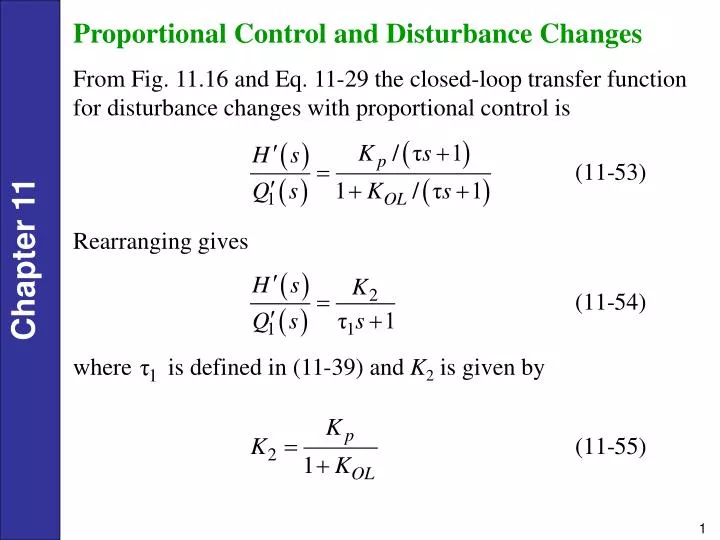
Proportional Control and Disturbance Changes From Fig. 11.16 and Eq. 11-29 the closed-loop transfer function for disturbance changes with proportional control is Rearranging gives where is defined in (11-39) and K2 is given by
A comparison of (11-54) and (11-37) indicates that both closed-loop transfer functions are first-order and have the same time constant. • However, the steady-state gains, K1 and K2, are different. • From Eq. 11-54 it follows that the closed-loop response to a step change in disturbance of magnitude M is given by The offset can be determined from Eq. 11-56. Now since we are considering disturbance changes and for a step change of magnitude M. Thus,
PI Control and Disturbance Changes For PI control, . The closed-loop transfer function for disturbance changes can then be derived from Fig. 11.16: Clearing terms in the denominator gives Further rearrangement allows the denominator to be placed in the standard form for a second-order transfer function:
where For a unit step change in disturbance, , and (11-59) becomes For , the response is a damped oscillation that can be described by
PI Control of an Integrating Process Consider the liquid-level control system shown in Fig. 11.22. This system differs from the previous example in two ways: • the exit line contains a pump and • the manipulated variable is the exit flow rate rather than an inlet flow rate. In Section 5.3 we saw that a tank with a pump in the exit stream can act as an integrator with respect to flow rate changes because
Figure 11.22 Liquid-level control system with pump in exit line.
If the level transmitter and control valve in Eq. 11.22 have negligible dynamics, the Gm(s) = Km and Gv(s) = Kv. For PI control, . Substituting these expressions into the closed-loop transfer function for disturbance changes and rearranging gives where And KOL = KcKvKpKm with Kp = - 1/A.
Stability of Closed-Loop Control Systems Example 11.4 Consider the feedback control system shown in Fig. 11.8 with the following transfer functions: Show that the closed-loop system produces unstable responses if controller gain Kc is too large.
Figure 11.23. Effect of controller gains on closed-loop response to a unit step change in set point (example 11.1).