Download
1 / 61
770 likes | 2.05k Views
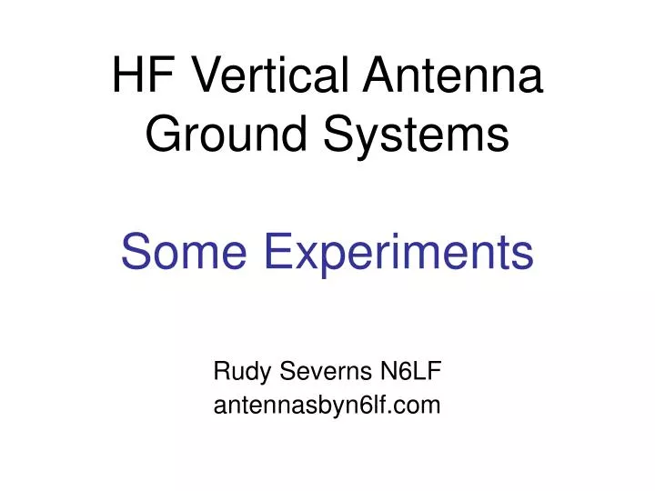
HF Vertical Antenna Ground Systems Some Experiments. Rudy Severns N6LF antennasbyn6lf.com. We’ve been using verticals for over 100 years. Is there really anything new to be said about ground systems for verticals? Yes!

E N D
HF Vertical Antenna Ground SystemsSome Experiments Rudy Severns N6LF antennasbyn6lf.com
We’ve been using verticals for over 100 years. • Is there really anything new to be said about ground systems for verticals? • Yes! • Little attention has been given to HF (2-30 MHz) ground systems like those used by amateurs. • Soil behavior at HF is different from BC.
Typical amateur antennas use: • radials lying on the ground surface, • or elevated radials, • and/or small numbers of radials, • short loaded verticals
Some typical questions • How much of ground system is it worth putting down? • What will I gain (in dB) by adding more radials? • Does it matter if I lay the radials on the ground surface? • Are a few long radials useful? • Are four elevated radials really as good as lots of buried radials? • How well do “gullwing” elevated radials work?
We can use modeling or calculations to answer these questions but most people don’t have a lot confidence in mathematical exercises. • High quality field measurements on real antennas are more likely to be believed. • Over the past year I have done a series of experiments on HF verticals with different ground systems. • That is the subject of today’s talk.
What’s the purpose of the ground system? • It’s there to reduce the power absorbed by the soil close to the antenna (within a ¼-wave or so). • The ground system increases your signal by reducing the power dissipated in the soil and maximizing the radiated power. • Any practical ground system will not affect the radiation angle or far-field pattern!
Power transmission antenna 1 antenna 2 antenna equivalent circuit
E and H fields around a vertical ground soil equivalent
The Electric Field (E) + E field V - resistor
Relative Ground Current loss is proportional to I2!
Electric Field Intensity Near The Base • f = 1.8 MHz and Power = 1500 W
Power transmission antenna 1 antenna 2 antenna equivalent circuit
Measurement schemes • The classical technique is to excite the test antenna with a known power and measure the resulting signal strength at some point in the far field (>2.5 wavelengths for 1/4-wave vertical). • This approach takes great care and good equipment to make accurate measurements.
The modern alternative is to use a vector network analyzer (VNA) in the transmission mode. This approach is capable of reliable measurements to <0.1 dB. The VNA will also give you the input impedance of the antenna at the feed-point. S21 rx antenna test antenna
The first experiment was a 160 m, ¼-wave wire vertical with two ground stakes and 4 to 64 radials. • Measurements were made with a spectrum analyzer as the receiver.
Test Results delta gain = 2.4 dB
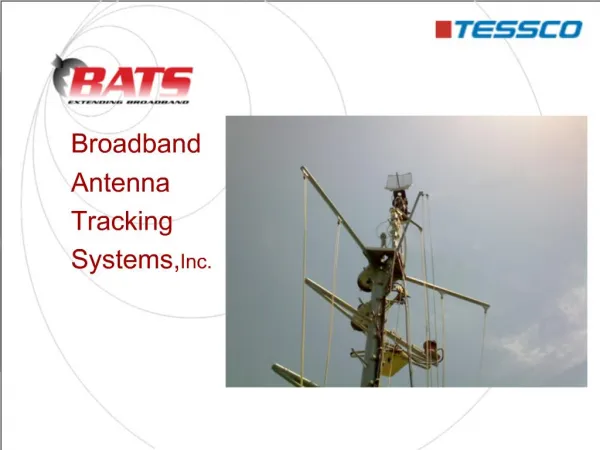
Receiving antenna at 40’ N7MQ holding up the mast!
Network analyzers note, automatic, organic, heating system Homebrew N2PK HP3577A with S-box
Test antennas • A 1/4-wave 40m tubing vertical. • An 1/8-wave 40m tubing vertical with top loading. • An 1/8-wave 40m tubing vertical resonated with a base inductor. • A 40 m Hamstick mobile whip. • SteppIR vertical
Caution! • Your mileage may vary! • My soil is pretty good but for poorer soils expect more improvement with more radials. • The degree of improvement will also depend on the frequency: • soil characteristics change with frequency, • at a given distance in wavelengths the field intensity increases with frequency.
Field day scenario • You want a 40 m vertical for field day. • ¼-wave = 33’. So you start with about 33’ of aluminum tubing for the radiator and four 33’ wire radials. • You erect this, with the radials lying on the ground and it’s resonant well below the band! • What to do? • Nothing, use a tuner and move on, • Shorten vertical until it’s resonant, • add more radials • or, shorten the radials until the antenna is resonant. • Which is best?
Lets do an experiment: • isolate the base of the antenna with a common mode choke (a balun). • lay out sixty four 33’ radials and adjust the vertical height to resonate (reference height). • remove all but four of the radials • Measure S21 with the reference height. • Measure S21 with the vertical shortened to re-resonate. • Measure S21 with the reference height as we shorten the radials.
Direct measurement of several options • Do nothing: G= 0 dB • Shorten height: G=-0.8 dB • Shorten radials: G=+3.5 dB • Use 16 radials: G=+4 dB • Use 64 radials: G=+5.9 dB
An observation • When you have only four radials the test results are always a bit squirrelly: • small variations in radial layout, • coupling to other conductors, • like the feed-line, • all effect the measurements making close repeatability difficult between experiments. • The whole system is very sensitive to everything! • This nonsense goes away as the number of radials increases!