Download
1 / 30
320 likes | 440 Views
Improving the beam quality in LMA fibers by providing a passive ring in the cladding. Emil Voiculescu,Technical University of Cluj, RO, Mircea Hotoleanu, Liekki Oy, FIN, Gabor Csipkes TUCN, RO. The problem.

E N D
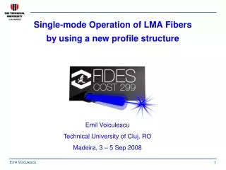
Improving the beam quality in LMA fibers by providing a passive ring in the cladding Emil Voiculescu,Technical University of Cluj, RO, Mircea Hotoleanu, Liekki Oy, FIN, Gabor Csipkes TUCN, RO
The problem • As the diameter of the LMA fiber grows, a multimode operation is always more likely to happen. Beam quality being of interest, it would be better that the fundamental mode prevails. A single mode operation would be ideal. • By playing with the index profile concurrently with the doping profile, a sufficient narrowing of the fiber core has been obtained, associated with substantial attenuation of the higher order modes. As reported at Les Houches meeting, in order to attenuate the higher order modes one have to bypass the D-point underneath.
The D-point • The D-point is a deliberate depression in the index profile around a /2 ( a is the core radius), and having an index height of circa ( n1 – n2 ) / 2. • As the fiber core diameter grows, the D-point descends. For really large core fibers ( 2a ≥ 40 μm ), the index profile should be concave to preserve single-mode operation.
Example : Depression point position obtained for 30μm-thick core LMA fibers to get sufficient attenuation of the higher order modes The index profile has to fit the shaded area
n – the refractive index Short recap : main parameters of interest n1 – n2 − profile height Δ = ( n1 – n2 ) / n1 ≤ 1 % NA = √(n12 – n22) ≈ 0.07 Δ = NA2/2n12 n2= nSiO2 = 1.4573 – index of pure silica n1 = √(NA2+n22)= 1.45898 n1 – n2 = 0.00168
Does the index profile depression represent the solution to the problem ? • Not quite • By virtually narrowing the core, the effective mode area drops, and that is not always accepted. With high power applications for sure • That is why we looked towards different ways to reject the higher order modes
Cladding passive ring Main parameters to deal with • This possibility has been suggested by Dr M Hotoleanu in May, in order to be implemented at Liekki, • and it became our current task. • It implies a step-index profile, and a flat doping of the core.
We got the following hints : • Try large index heights in the ring ( 6x or so) • Vary the ring thickness b1 – b2 • Look for the best position of the ring ( vary width w) • Flat doping is more likely to be used, however playing with the dopant is advisable • Numerical Aperture : around 0.07 • (later) : Optimize possible results by trimming nco- ncl
The mode effective area The scalar wave equation contains – the scalar field function for the fundamental mode, the free- space wave number k = 2π/λ, the propagation constant β and the refraction index profile n(r). • The spot radius , also called effective modal spot size , is : and the LAD gives all data to compute it. • The Effective Area is and • the Mode Field Diameter is . Mode effective area to core area ratio might be called the normalized effective core ( or normalized coverage) [ %].
The setup used for simulation • Chosen Ytterbium Doped fibers : 20μm- and 25μm-core, double-clad fibers, • code Yb 1200 -25 -250DC, provider Liekki Oy • Other data : λs = 1.064μm, Ps = 300 mW, λP = 976 nm, Pp = 30 W • Simulator Used : Recently released LAD 3.3
First we got that : • Large Index Height in the Ring Does Not Help,• Narrow Ring ( 1 μm or so ) – does not help, as we got :• Many modes scrambled together ( 6 to 8),• Power in modes M2, M3 or M6 comparable with the M1 power, or 2 – 3 times higher. Then : • neither it helps to narrow the groove in the index profile under 1μm, • nor to shrink the ring to the core.
This index profile represents a result Characteristics : Core diameter 2a = 20 μm, Core index height n1 – n2 = 0.0168 Groove width w = 2μm, Ring index height : Δh = 0.0032, Ring width w = 2 μm
Power distribution among modes • At the fiber input, all modes have the same power, i.e : 300mW / 6 =50mW; • At the output end, the most powerful mode rejection ratio is : P1 / Pmax = P1 / P6 = 7.4 dB, to be improved; • The Mode field diameter over the core diameter is : MFD / Dco = 76.5 % , the effective mode area in M1 over the area of the core Aeff / Aco = 58.5 %.
As specified in the fiber manufacturer task, a flat doping has been considered : The dopant concentration was 1.56 x 1026 / m3, as implicit with the simulator
By pushing the ring 1 μm outside the fiber axis a slightly different regime results →
More distant groove / same 2 μm width • This time the rejection of M6 (most powerful higher-order mode) grows to 8.94 dB, which is acceptable; • The MFD is 13.42 μm for a 20 μm wide core, which gives Aeff / Aco = 45% − to be improved.
Similar results ► Similar results have been experienced with thicker cores, as for instance with the Yb-1200-25-250DC fiber, having a 25μm diameter core : ▪ Higher order modes have been attenuated to P1 / Pmax = P1 / P2 = 5.7dB, ▪ MFD / 2a = 15.94μm / 25μm = 63.8%, core coverage Aeff / Aco = 40.6%.
To summarize : ► By narrowing the ring to 1 μm, M2 raises to a level of (P1− 3dB), which is not acceptable. ► By widening the ring to 4μm, modes M6and M5 take over the fundamental mode. ► The same happens by raising up the ring height Δh to 0.004 (instead of the previous value of 0.0032) of the differential index : M6 overcomes M1. ►Great results can be obtained by taking wider cores and placing the ring INSIDE the core. Actually such tries have no practical significance.
Eventually, the case when the ring sticks to the core: A modest result : 5 modes, less than 6dB attenuation of the most powerful mode, MFD = 13.6μm,MFD / 2a = 0.68, Aeff / Aco = 46%. Technologically not attractive (difficult).
Next : Finding the best index profile The following attempts have been made: 1. The differential index in the core n1 – n2 has been varied among rated 0.00168 (most usual NA = 0.07), and 0.00182 maximum; a flat peak of the higher order modes rejection has resulted. 2. The height of the index difference in the ring Δh, has been varied in accordance with the n1 – n2 adjustments, among 0.003 and 0.0033, in 10 steps.
The strongest rejection of mode M6 (and M2)gives the necessary index difference in the core n1-n2 = 0.001765 NB : Δh = 0.0032
The optimal ring index difference, obtained for a n1-n2 = 0.00175 step in the core, readsΔh = 0.00317 NB : Best index difference in the core n1-n2 = 0.001765
For these quantities the following power distribution among modes results: Remarkably, modes M2 and M6 overlap as they change places (positions) exactly on the peak
Conclusion • This time most powerful higher modes are M2 and M6, and their attenuation is P1 / Pmax = 9.2 dB. Empirical criteria suggest that around 10 dB of attenuation of any mode will do in practice. • The MFD is 14.72 μm for a 20 μm diameter of the core, meaning that MFD / 2a = 73.6%. • The normalized effective area is Aeff / A co = 54.2%.
A top-view might give a qualitative idea about the core coverage
Also the axial power distribution is computed as in the following diagram showing a peak power density of 5 mW /μm2
Lower levels of power densities are shown in the strongest higher-order modes
Conclusions • A passive ring in the cladding is of great help in rejecting the higher-order modes, and this method can be applied to a large range of LMA fibers. • Best results are achieved for core diameters in the range from several microns to 20-25μm • By slightly sliding the ring toward the cladding ( or toward the fiber axis) significant changes take place : • A ring closer to the core provides a higher effective area • A more distant ring might increase the higher order modes rejection, but that comes at the price of lower effective area • The cladding ring procedure is of interest for Liekki, and it is very likely that it would be put into production soon • This material will be reported to the next Photonic West Conference