Download
1 / 28
280 likes | 289 Views
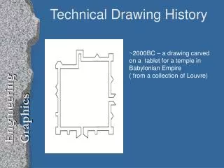
Technical Drawing in Photonics Lesson 7 Primitive notions of geometric space. Projecting space onto a plane. Orthogonal projection. The double orthogonal projection system (descriptive geometry). Projection of a point. Projection of a line. Representation of a plane. Dr. Zsolt István Benkő.

E N D
Technical Drawing in Photonics • Lesson 7 • Primitive notions of geometric space. • Projecting space onto a plane. Orthogonal projection. The double orthogonal projection system (descriptive geometry). • Projection of a point. Projection of a line. Representation of a plane. Dr. Zsolt István Benkő TAMOP-4.1.1.C-12/1/KONV-2012-0005 project „Preparation of the concerned sectors for educational and R&D activities related to the Hungarian ELI project”
Lesson 7 P • The primitive notions of geometric space are: • points, • lines, • planes. All are undefined terms. The point is the most fundamental object: it has zero dimension (no size), it is represented by a dot and named by a capital letter. point P Technical drawing in Photonics
Lesson 7 A e B line segment AB The line consists of infinitely many points. It is a one dimensional object. It has infinite length but has no width and height. It extends to infinitely far in two opposite directions. It is named usually by a small letter. A line segment may be named by the letters of the two endpoints. line e Every two distinct points denote a line and a line segment as well. If a third point fits to the line denoted by two points, then the points are called collinear. Technical drawing in Photonics
Lesson 7 A plane is an infinite set of points forming a connected flat surface. It extends infinitely far in all directions. It is a two dimensional object: it has infinite length and infinite width but no height. It is represented usually by a four sided figure and named by a capital letter. plane S A plane can be denoted by two intersecting lines or by a line and a non-fitting point or by three not collinear points. Technical drawing in Photonics
Lesson 7 Sometimes it is needed that a spatial object should be presented on paper or on a screen. In other words the three-dimensional space should be represented on a two-dimensional plane. This process is called projection. In a projection system projecting rays are used. (They are treated like idealized light rays.) Technical drawing in Photonics
Lesson 7 point on object object projected point on plane projection plane ray A projection ray originates from a point of the spatial object and where it hits the plane there would be the projection of the point. Technical drawing in Photonics
Lesson 7 C central parallel There are many types of projection. The most common ones are the central projection and the parallel projection. In a central projection all the rays run into a single point called the center of projection. In a parallel projection all the rays are parallel. Technical drawing in Photonics
Lesson 7 A special parallel projection is called the orthogonal projection. The rays are normal to the projection plane. In parallel projection if a spatial object is in a parallel position to the plane then the real measures can be obtained. Technical drawing in Photonics
Lesson 7 With a single projection plane only two dimensions could be recovered. If all spatial dimensions are needed (e.g. for production) then two projection planes are required. The most widely used is the double orthogonal projection system (other names: descriptive geometry; Monge geometry). It has two perpendicular projection planes. One is usually horizontal and the other is vertical. Their intersection is a line called the axis of projection or projection axis. A spatial point (P) is projected to the horizontal plane by a normal ray: it is the top-view or 1st view (P’). The same point is projected to the vertical plane by a normal ray: it is the front-view or 2nd view (P”). Technical drawing in Photonics
Lesson 7 The P, P’ , P” points and a point of the axis denote a rectangle called the projection rectangle. (Two sides of it are the projecting rays.) The horizontal plane then rotated down around the axis into the vertical plane. The projection rectangle transforms into a line which is perpendicular to the axis. The top-view (1st view) and the front-view (2nd view) of the same spatial point is always connected by a line normal to the axis. Sometimes this line is called ”organizer” or ”organizer line”. Technical drawing in Photonics
Lesson 7 ray P” P P’ axis Basic arrangement Technical drawing in Photonics
Lesson 7 P” axis P’ Basic arrangement Technical drawing in Photonics
Lesson 7 P” axis P’ Basic arrangement Technical drawing in Photonics
Lesson 7 Basic arrangement Technical drawing in Photonics
Lesson 7 II I III IV The projection planes are infinite. They divide the space into 4 quadrants. They are marked by roman numbers. The observer always views towards the axis. The closest quadrant to the observer is quadrant I. Technical drawing in Photonics
Lesson 7 P point is in quadrant I: P Technical drawing in Photonics
Lesson 7 Q point is in quadrant II: Q Technical drawing in Photonics
Lesson 7 R point is in quadrant III: R Technical drawing in Photonics
Lesson 7 S point is in quadrant IV: S Technical drawing in Photonics
Lesson 7 The points in the projection. P” Q” R’ Q’ x1,2 S” S’ P’ R” Technical drawing in Photonics
Lesson 7 e” e” e x1,2 e’ e’ Projecting a line Technical drawing in Photonics
Lesson 7 Projecting a line Technical drawing in Photonics
Lesson 7 f” x1,2 T1 T2 f’ Trace on a plane Technical drawing in Photonics
Lesson 7 e” f” x1,2 f’ e’ 1st ray 2nd ray Special lines: rays Technical drawing in Photonics
Lesson 7 f” e” x1,2 f’ e’ 1st main line 2nd main line Special lines: main lines Technical drawing in Photonics
Lesson 7 g” f” x1,2 f’ g’ Representation of a plane Technical drawing in Photonics
Lesson 7 t2 x1,2 t1 Representation of a plane Technical drawing in Photonics
Lesson 7 • References • Ocskó Gy., Seres F.: Gépipari szakrajz, Skandi-Wald Könyvkiadó, Budapest, 2004 • Lőrincz P., Petrich G.: Ábrázoló geometria, Nemzeti Tankönyvkiadó Rt., Budapest, 1998 • Pintér M.: AutoCAD tankönyv és példatár, ComputerBooks, Budapest, 2006 Technical drawing in Photonics