Download
1 / 52
520 likes | 636 Views
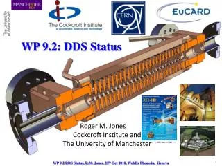
Status and Prospects for the CLIC DDS. Roger M. Jones Cockcroft Institute and The University of Manchester. International Workshop on Linear Colliders (IWLC), 18-22 Oct 2010, CERN, Geneva. Wake Function Suppression for CLIC -Staff. 2. FP420 –RF Staff.

E N D
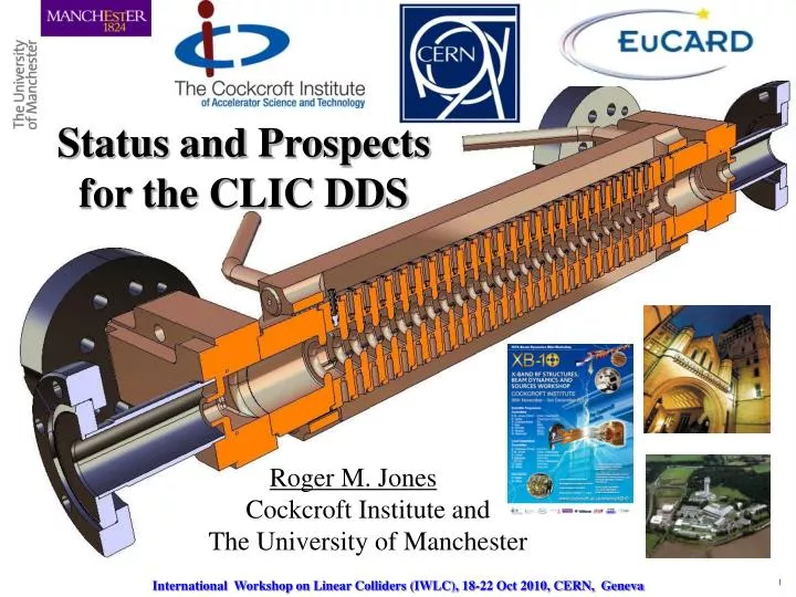
Status and Prospects for the CLIC DDS Roger M. JonesCockcroft Institute andThe University of Manchester International Workshop on Linear Colliders (IWLC), 18-22 Oct 2010, CERN, Geneva
Wake Function Suppression for CLIC -Staff 2. FP420 –RF Staff • Roger M. Jones (Univ. of Manchester faculty) • Alessandro D’Elia (Dec 2008, Univ. of Manchester PDRA based at CERN) • Vasim Khan (PhD student, Sept 2007) • Nick Shipman (PhD student Sept 2010, largely focused on breakdown studies) • Part of EuCARD ( European Coordination for Accelerator Research and Development) FP7 NCLinac Task 9.2 • Major Collaborators: W. Wuensch, A. Grudiev, I. Syrachev, R. Zennaro, G. Riddone (CERN) V. Khan, CI/Univ. of Manchester Ph.D. student Finishing 2011!? A. D’Elia, CI/Univ. of Manchester PDRA based at CERN (former CERN Fellow). N. Shipman, NEW! CERN/CI/Univ. of Manchester Ph.D. student
Overview Three Main Parts: Review of salient features of manifold damped and detuned linacs. • Initial designs (three of them). CLIC_DDS_C. • Further surface field optimisations CLIC_DDS_E(R). • Finalisation of current design. Based on moderate damping on strong detuning. Single-structure based on the eight-fold interleaved for HP testing CLIC_DDS_A • Concluding remarks and future plans.
1. Introduction –Present CLIC baseline vs. alternate DDS design • The present CLIC structure relies on linear tapering of cell parameters and heavy damping with a Q of ~10. • Wake function suppression entails heavy damping through waveguides and dielectric damping materials in relatively close proximity to accelerating cells. • Choke mode suppression provides an alternative, but may negatively impact Rsh • A viable alternative is presented by our CLIC_DDS design - parallels the DDS developed for the GLC/NLC, and entails: 1. Detuning the dipole bands by forcing the cell parameters to have a precise spread in the frequencies –presently Gaussian Kdn/df- and interleaving the frequencies of adjacent structures. 2. Moderate damping Q ~ 500-1000
1. Features of CLIC DDSAccelerating Structure Acceleration cells Beam tube Manifold HOM coupler High power rf coupler • SLAC/KEK RDDS structure (left ) illustrates the essential features of the conceptual design • Each of the cells is tapered –iris reduces (with an erf-like distribution –although not unique) • HOM manifold running alongside main structure removes dipole radiation and damps at remote location (4 in total) • Each of the HOM manifolds can be instrumented to allow: 1) Beam Position Monitoring2) Cell alignments to be inferred
1. Determination of Cell Offset From Energy Radiated Through Manifolds –GLC/NLC Dots indicate power minimisation
1. GLC/NLC Exp vs Cct Model Wake Qcu DS ASSET Data RDDS1 DDS3 (inc 10MHz rms errors) DDS1 H60VG4SL17A/B -2 structure interleaved RDDS1 Conspectus of GLC/NLC Wake Function Prediction and Exp. Measurement (ASSET dots) Refs: 1. R.M. Jones,et al, New J.Phys.11:033013,2009. 2. R.M. Jones et al., Phys.Rev.ST Accel. Beams 9:102001, 2006. 3. R.M. Jones, Phys.Rev.ST Accel. Beams, Oct.,2009.
1. CLIC Design Constraints • Beam dynamics constraints • For a given structure, no. of particles per bunch N is decided by the <a>/λ and Δa/<a> • Maximum allowed wake on the first trailing bunch • Wake experienced by successive bunches must also be below this criterion 1) RF breakdown constraint 2) Pulsed surface temperature heating 3) Cost factor Ref: Grudiev and Wuensch, Design of an x-band accelerating structure for the CLIC main linacs, LINAC08
2.0 Initial CLIC_DDS Designs Three designs Initial investigation of required bandwidth to damp all bunches (~3GHz) –succeeds to suppress wakes, fails breakdown criteria! New design, closely tied to CLIC_G (similar iris a), necessitates a bandwidth of ~ 1 GHz. Geometry modified to hit bunch zero crossings in the wakefield -succeeds from breakdown perspective, tight tolerances necessary to suppress wakes! Relaxed parameters, modify bunch spacing from 6 to 8 rf cycles and modify bunch population. Wake well-suppressed and seems to satisfy surface field constraints. CLIC_DDS_C (f ~ 3.6, 13.75%) –SUCCESS (on suppressing wakes and meeting breakdown criteria) Three designs Initial investigation of required bandwidth to damp all bunches (~3GHz) –succeeds to suppress wakes, fails breakdown criteria! Three designs Initial investigation of required bandwidth to damp all bunches (~3GHz) –succeeds to suppress wakes, fails breakdown criteria! New design, closely tied to CLIC_G (similar iris a), necessitates a bandwidth of ~ 1 GHz. Geometry modified to hit bunch zero crossings in the wakefield -succeeds from breakdown perspective, tight tolerances necessary to suppress wakes!
2.1 Initial CLIC_DDS Design –f determination Bandwidth Variation Variation Lowest dipole ∆f ~ 1GHz Q~ 10 CLIC_DDS Uncoupled Design CLIC_G
2.3 Relaxed parameters tied to surface field constraints (f/<f> = 13.75 %) Uncoupled parameters Cct Model Including Manifold-Coupling Cell 1 Cell 24 • Iris radius = 4.0 mm • Iris thickness = 4.0 mm , • ellipticity = 1 • Q = 4771 • R’/Q = 11,640 Ω/m • vg/c = 2.13 %c • Iris radius = 2.13 mm • Iris thickness = 0.7 mm, • ellipticity = 2 • Q = 6355 • R’/Q = 20,090 Ω/m • vg/c = 0.9 %c • Employed spectral function and cct model, including Manifold-Coupling, to calculate overall wakefunction.
2.3 Structure Geometry: Cell Parameters Structure GeometryCell parameters Iris radius Iris radius R amin, amax= 4.0, 2.13 b t/2 Cavity radius Cavity radius a1 Rc a bmin, bmax= 10.5, 9.53 a Fully Interleaved 8-structures Sparse Sampled HPT (High Power Test) a+a1 L
2.3 Relaxed parameters –full cct model Coupled 3rd mode Coupled 3rd mode Uncoupled 2nd mode Uncoupled 2nd mode Uncoupled 1st mode Uncoupled 1st mode Avoided crossing Avoided crossing Uncoupled manifold mode Light line Light line Uncoupled manifold mode Uncoupled 2nd mode Coupled 3rd mode Uncoupled 1st mode Avoided crossing Light line Uncoupled manifold mode Mid-Cell First Cell • Dispersion curves for select cells are displayed (red used in fits, black reflects accuracy of model) • Provided the fits to the lower dipole are accurate, the wake function will be well-represented • Spacing of avoided crossing (inset) provides an indication of the degree of coupling (damping Q) End Cell
2.3 Summary of CLIC_DDS_C Dipole mode Manifold mode Manifold ∆f=3.6 σ =2.3 GHz ∆f/fc=13.75% Coupling slot 24 cells No interleaving Meets design Criterion? ∆fmin = 8.12 MHz ∆tmax =123 ns ∆s = 36.92 m ∆fmin = 65 MHz ∆tmax =15.38 ns ∆s = 4.61 m 192 cells 8-fold interleaving 192 cells 8-fold interleaving
3. CLIC_DDS_E • Enhanced H-field on various cavity contours results in unacceptable T (~65° K). • Can the fields be redistributed such that a ~20% rise in the slot region is within acceptable bounds? • Modify cavity wall • Explore various ellipticities (R. Zennaro, A. D’Elia, V. Khan)
3. CLIC_DDS_E Elliptical Design b a Circular Elliptical Convex Concave Square
3. CLIC_DDS_E Elliptical Design –E Fields Circular Square Single undamped cell Iris radius=4.0 mm Convex ellipticity Concave ellipticity ε=-8.28 ε=-2.07 ε=-4.14
3 CLIC_DDS_E Elliptical Design, Single Undamped Cell Dependence of Fields on Iris radius = 4. 0 mm Iris thickness = 4.0 mm Chosen design
3. CLIC_DDS_E Single-Cell Surface Field Dependence on ε Optimisation of cavity shape for min • Iris radius ~4mm. For both geometries • Averaging surface H over contour =1.38 Rectangular ( =∞) Circular ( =1) Circular cell ε=1.38 ε=0.82 ε =0.82 Manifold-damped single cell ε=1.38 ε=0.41 Optimised parameters for DDS2 ε=2.07 ε=4.14 Undamped cell
3. CLIC_DDS_E, Optimisation of: , ∆f and Efficiency Efficiency ∆T • Optimisation of parameters based on manifold damped structures. • Vary half-iris thickness. • 3-cell simulations, with intermediate parameters obtained via interpolation. • Choose parameters with minimal surface E-field, pulse temperature rise, and adequate efficiency. Pin ∆f dipole Chosen optimisation (CLIC_DDS_E)
3. CLIC_DDS_E: Detailed Geometry r2 Radius = 0.5 mm h1 2*r2 r1 a2 h g=L - t r1 r1+h+2r2 a1 Rc t= 2a2 a L
3. Impact on Parameters: CLIC_DDS_C to CLIC_DDS_E DDS2_E DDS1_C DDS1_C DDS2_E
3. CLIC_DDS_E -Fundamental Mode Parameters DDS1_C DDS_E DDS_E Vg Q DDS1_C R/Q DDS1_C DDS1_C DDS_E DDS_E • Group velocity is reduced due increased iris thickness • R/Q reduced slightly • Surface field and T reduced significantly by using elliptical cells DDS1_C Es Hs DDS_E
3. Wake Function for CLIC_DDS_E -Dipole Circuit Parameters DDS_C DDS_E Cct DDS_C DDS_E DDS_E DDS1_C • Avoided crossing x is significantly reduced due to the smaller penetration of the manifold. • Some re-optimisation could improve this Avoided Crossing ∆f=3.5 σ =2.2 GHz ∆f/fc=13.75% a1=4mm a24=2.3mm
3. Consequences on Wake Function Spectral Function Wake Function DDS1_C DDS2_E
4. CLIC_DDS_E: Modified Design Based on Engineering Considerations DDS2_ER DDS2_E Rounding necessitates reducing this length (moves up) Rc Rounding • To facilitate machining of indicated sections, roundings are introduced (A. Grudiev, A. D’Elia). • In order to accommodate this, Rc needs to be increased DDS2_ER. • Coupling of dipole modes is reduced and wake-suppression is degraded. How much?
Cell # 1 Uncoupled Dipole mode Uncoupled manifold mode Cell # 24 4. CLIC_DDS_ER Dispersion Curves Uncoupled 2nd Dipole Mode Cell # 1 Avoided crossing Light Line Light line Cell # 24
4. CLIC_DDS_E vs CLIC_DDS_ER Wakefield Spectral Function Wakefunction CLIC_DDS_E :Rc=6.2 - 6.8 mm (optimised penetration) • CLIC_DDS_ER : Rc=6.8 mm const (a single one of these structures constitutes CLIC_DDS_A, being built for HP testing) • Wakefield suppression is degraded but still within acceptable limits.
4. CLIC_DDS_A: Structure Suitable for High Power Testing • Info. on the ability of the 8-fold interleaved structure to sustain high e.m. fields and sufficient T can be assessed with a single structure. • Single structure fabricated in 2010/1st quarter 2011, CLIC_DDS_A, to fit into the schedule of breakdown tests at CERN. • Design is based on CLIC_DDS_ER • To facilitate a rapid design, the HOM couplers have been dispensed with in this prototype. • Mode launcher design utilised • SRF design complete! • Mechanical drawings, full engineering design completed! • Qualification end cells fabricated. Recently received (Oct 15 2010!)!
4. CLIC_DDS_A: Structure Suitable for High Power Testing • Non-interleaved 24 cell structure –first structure of 8-fold interleaved structure chosen. • High power (~71MW I/P) and high gradient testing • To simplify mechanical fabrication, uniform manifold penetration chosen Cell # 24 Cell # 1 Illustration of extrema of a 24 cell structure
4. CLIC_DDS_A Parameters Esur Max. Values Esur=220 MV/m ∆T = 51 K Pin= 70.8 Eacc_UL=131 MV/m Sc=6.75 W/μm2 RF-beam-eff=23.5% 35*Sc Eacc Pin ∆T CLIC_G Values Esur=240 MV/m ∆T = 51 deg. Pin= 63.8 Eacc_UL=128 MV/m Sc=5.4 W/μm2 RF-beam-eff=27.7% Dashed curves : Unloaded condition Solid curves: Beam loaded condition
4. CLIC_DDS_A Wake 24 cells No interleaving • Wake of a non-interleaved 24 cell structure –first structure of 8-fold interleaved structure chosen. • Motivated by high gradient testing • Wake is measurable and provides a useful comparison to simulations (but will not, of course, meet beam dynamics criteria) Undamped Qavg ~1700 Damped 24 cells No interleaving
4. Matching CLIC_DDS_A • Firstly, match-out either end of structure with regular cells: • Structure for test will utilise a mode launcher • Initially, simulate a structure with one regular cell and two matching cells at either end and we study the minima in S11 as a function of the geometrical parameters of the matching cells (a, L –adopt L variation, rather than b, from space considerations) • Add additional (2, then 3) identical standard cells (const. imp) and follow the same procedure and modify parameters of matching cells to minimise S11 • The matching condition (on a, L) is that which coincident with all 3 simulations. • Secondly, once complete, match-out the full, tapered structure based on this match. I/P
4. CLIC_DDS_A Axial E-Field Surface E-Field • Match-out the full, tapered structure • E-field and S11 shown E-field Port11 Port 2 7.5 Beam 7 Matching cell Ez (V/m x104) Es (V/m x104) 5.0 0 300 0 z (mm) 225 z (mm) A. D’Elia ~198.6mm
S12 S22 4. CLIC_DDS_A S Params Q 11.988 12 S11 -48.2dB@ 11.9944GHz 0dB -50dB /2 (GHz) 6165 @ 11.9944GHz
4. Mechanical Eng. Design of DDS_A Water pipes for cooling Vacuum flange Power output Tuning holes Power input Vacuum flange Cutaway-view Beam V.Soldatov
4. Cell Qualification of CLIC_DDS_A x (mm) -1.6 0.3 • VDL (NL) have machined and measured several cells –end cells. New!(recvd by CERN Oct 2010) • Global profiles made with optical Zygo machine are illustrated for disk 24 • Design, tolerance bounds and achieved profile shown • ETA of all cells –December 2010 • Bonding of complete structure by 1st quarter of 2011. 1.5mm Quarter cell contours Measured Cell edge contours Specified Measured Specified 0.5 mm G. Riddone
4. Cell Qualification of CLIC_DDS_A • Local profile made with an optical Zygo machine • Local profiles indicate < 50nm variation in surface flatness • Cell 24 displayed +40 nm -40 nm G. Riddone
5. Work in Progress/R&D Opportunities Standard DDS Manifold Additional Manifold I/P at /2=15.9GHz • CLIC_DDS_A is equipped with mode launchers • CLIC_DDS_B includes full HOM ports • Initial studies on matching the HOM coupler for CLIC_DDS_B in progress (dipole band ~ 15.9 GHz – 18 GHz) • Moving to a high phase advance (HPA) structure allows other parameters to be optimised • 5/6 phase advance structure design in progress (for initial design see Linac2010) • In the HPA design further features being explored • Additional manifold (8) Sic EnhancedCoupling Sic • Influence of SiC rods on overall Q
5. Final Remarks • CLIC_DDS_A : RF (including mode launcher matching cells) and mechanical design has been completed. • Qualifications cells fabricated (VDL)–all cells by last quarter 2010 • Structure will be subsequently bonded in the first quarter of 2011, --ready for high power testing in 2011 at the CLIC test stand. • CLIC_DDS_B: Includes HOM couplers and interleaving. HOM coupler design in progress. • New CLIC_DDS R&D in progress: • HPA: High phase advance design is being studied. It Allows optimisation of the remaining parameters –minimise surface fields, wakefields at stipulated vg • Further optimisation is being explored by implementing additional manifolds and with the potential for the insertion of SiC rods to reduce the Q further
Acknowledgements CLIC DDS Related Pubs. R. M. Jones, et. al, PRST-AB, 9, 102001, 2006. V. F. Khan and R.M. Jones, EPAC08, 2008. V. F. Khan and R.M. Jones, LINAC08, 2008. V. F. Khan and R.M. Jones, Proceedings of XB08, 2008. R. M. Jones, PRST-AB, 12, 104801, 2009. R. M. Jones, et. al, NJP, 11, 033013, 2009. V. F. Khan and R.M. Jones, PAC09, 2009. V. F. Khan, et. al, IPAC10, 2010. V. F. Khan, et. al, LINAC10, 2010. • I am pleased to acknowledge a strong and fruitful collaboration between many colleagues and in particular, from those at CERN, University of Manchester, Cockcroft Inst., SLAC and KEK. • Several at CERN within the CLIC programme, have made critical contributions: W. Wuensch, A. Grudiev, I. Syrachev, R. Zennaro, G. Riddone (CERN). • Thanks to Walter for arranging this session!
ICFA X-Band UK Workshop • On the near horizon, December 2010, is the XB-10 workshop on accelerator structures, beam dynamics, and sources. • Cockcroft Inst., UK • Peer reviewed papers will be published in a NIMs A special issue. • Registration is still open and, you are invited to attend!
5. Spectral function Wake function